
Test bed for testing shear load of anchor rod and test method of test bed

A technology of shear load and test method, which is applied in the direction of applying stable shear force to test the strength of materials, etc., which can solve the problems of not being able to observe the deformation of the rod body, not being able to test the anchor rod to withstand the rock slip shear load, and not being able to directly test the shear load and other issues to achieve the effect of deepening mechanism research

Inactive Publication Date: 2014-10-08
TIANDI SCI & TECH CO LTD
View PDF6 Cites 7 Cited by
  • Summary
  • Abstract
  • Description
  • Claims
  • Application Information

AI Technical Summary

Problems solved by technology

However, the downhole test has the disadvantages that it can only test the axial force formed by the bolt under the comprehensive action of various external forces, and cannot directly test the shear load acting on the bolt when the rock layers are dislocated, nor can it observe the effect of the shear load. rod deformation
However, the shortcomings of the laboratory test are: it only reflects the shear performance of the bolt material when it is loaded with a standard shear die, lacks the test equipment for simulating the shear loading of the bolt by the dislocation between the downhole rock layers, and cannot test the bolt in the support state. The Ability of Anchor Bolt to Bear Shear Load of Rock Formation Sliding

Method used


Image

  • Test bed for testing shear load of anchor rod and test method of test bed

Examples


Embodiment Construction

[0030] Embodiments of the present invention will be further described in detail below in conjunction with the accompanying drawings and examples. The following examples are used to illustrate the present invention, but should not be used to limit the scope of the present invention.

[0031] In the description of the present invention, unless otherwise stated, the meaning of "plurality" is two or more; the terms "upper", "lower", "left", "right", "inner", "outer" , "front end", "rear end", "head", "tail", etc. indicate the orientation or positional relationship based on the orientation or positional relationship shown in the drawings, and are only for the convenience of describing the present invention and simplifying the description, rather than Nothing indicating or implying that a referenced device or element must have a particular orientation, be constructed, and operate in a particular orientation should therefore not be construed as limiting the invention. In addition, t...


PUM


Abstract

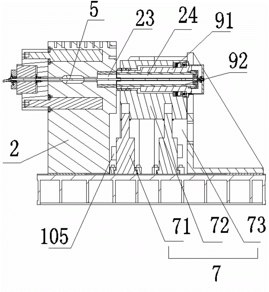
The invention relates to the technical field of mine support, and particularly relates to a test bed for testing the shear load of an anchor rod and a test method of the test bed. The test bed comprises an anchor rod for mine support, a working test board, a shearing device, a fixed drilling model, a follow-up drilling model and a hydraulic sensor, wherein the anchor rod is anchored in drilling holes of the fixed drilling model and the follow-up drilling model; the fixed drilling model is mounted on the working test board; the shearing device drives the follow-up drilling model to slide along the radial direction of the anchor rod; a shearing surface against the anchor rod is formed between the fixed drilling model and the follow-up drilling model; the hydraulic sensor is mounted on a loading oil way system of a shearing oil cylinder and used for testing the pressure of the oil cylinder system of the shearing device. Through the test bed, the test of the shearing resistance of the anchor rod in a laboratory is realized, a basis is provided for the theoretical study on the anchor rod support and the anchor rod support design in complicated stress conditions, and thus the test bed has great significance on deepening of the mechanism study on the anchor rod support and guaranteeing of the engineering safety.

Description

technical field [0001] The invention relates to the technical field of mine support, in particular to a test bench and a test method for testing the shear load of bolts. Background technique [0002] At present, bolt support has become a safe and efficient main support method for coal mine roadways, and has been widely promoted and applied in coal mine roadways in my country. Bolt support is to anchor the bolt in the coal rock body, tighten the nut at the end of the rod, apply prestress to the surrounding rock, and restrain the deformation, separation, expansion and slippage of the surrounding rock of the roadway. [0003] The stress situation in the actual working process of the bolt is very complicated. When the surrounding rock of the roadway is separated from the layer and deformed, some layers in the rock layer will inevitably slip and displace. The bolt that passes through the stratum and is anchored in the rock formation bears the shear load caused by the sliding of ...

Claims


Application Information

Patent Timeline
IPC IPC(8): G01N3/24
Inventor 康红普杨景贺吴拥政林健吕华文邵培森高富强
Owner TIANDI SCI & TECH CO LTD
Learn More