
Robojelly driven by axially parallel annular shape memory alloy

A technology of memory alloy and memory alloy wire, which is applied in the direction of non-rotating propulsion components, can solve the problems of complex structure and small movement range of bionic machine jellyfish, and achieve simple control, high bionic propulsion effect, and obvious bionic effect

Active Publication Date: 2014-10-08
HARBIN INST OF TECH
View PDF7 Cites 8 Cited by
  • Summary
  • Abstract
  • Description
  • Claims
  • Application Information

AI Technical Summary

Problems solved by technology

[0004] The present invention aims to solve the problems that the structure of the existing machine bionic jellyfish is complicated, and the range of movement of the bionic machine jellyfish is small, which is quite different from the bionic propulsion behavior of the real jellyfish, and further provides a machine driven by an axially parallel annular shape memory alloy jellyfish

Method used


Image

  • Robojelly driven by axially parallel annular shape memory alloy
  • Robojelly driven by axially parallel annular shape memory alloy
  • Robojelly driven by axially parallel annular shape memory alloy

Examples


specific Embodiment approach 1

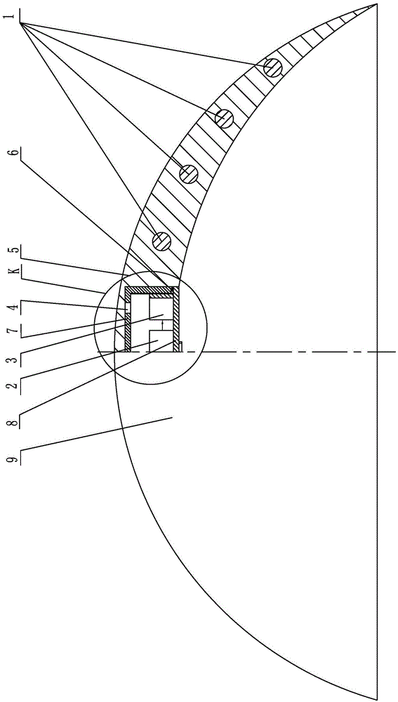
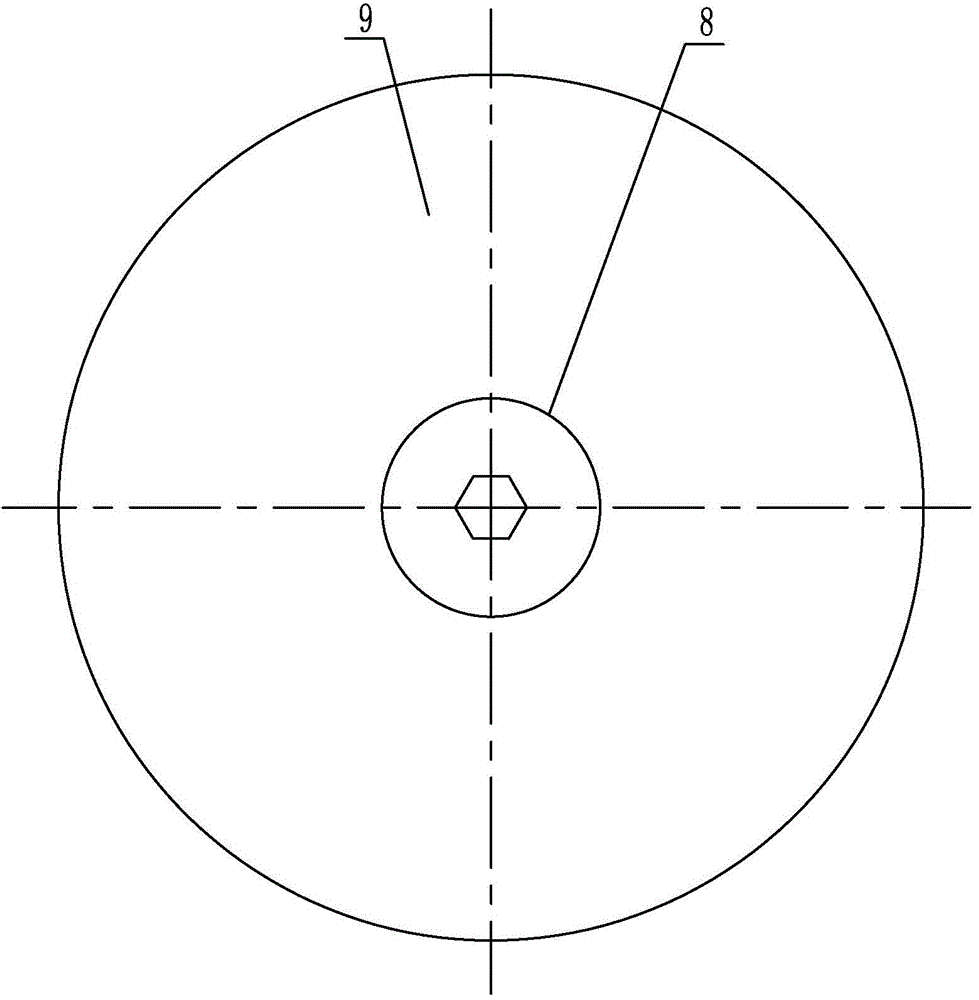
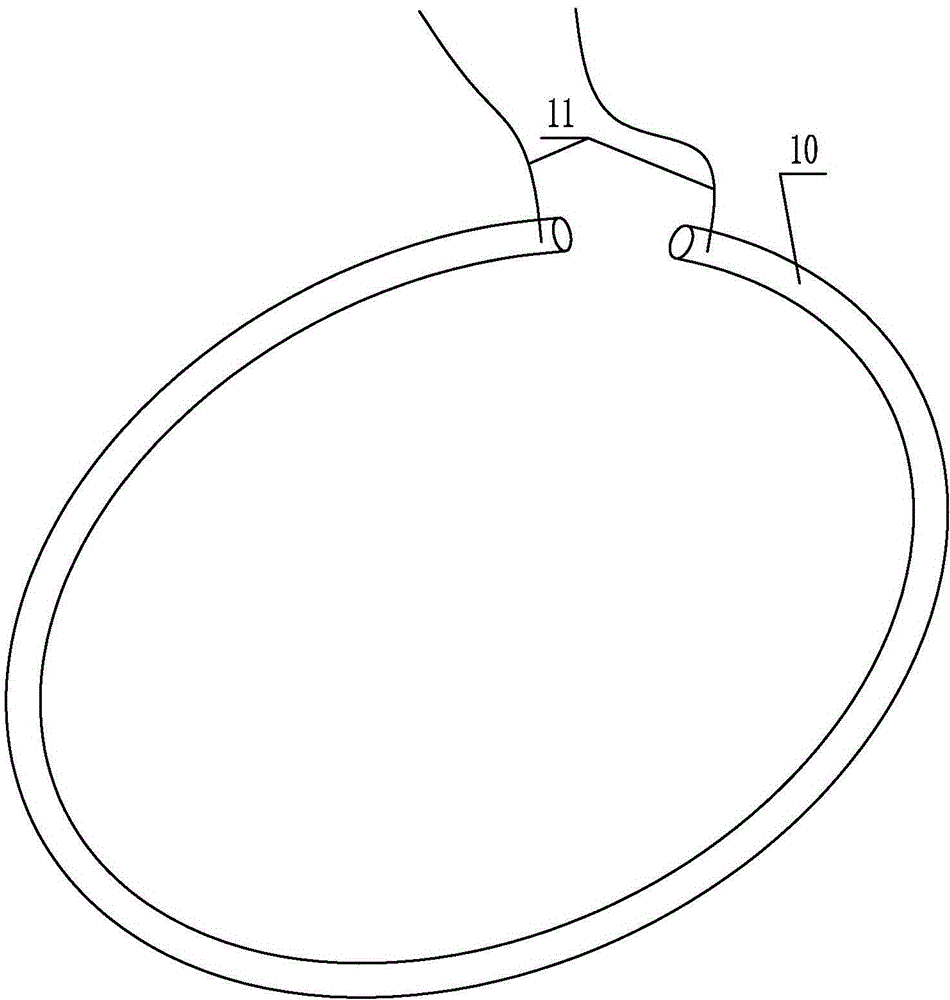
[0010] Specific implementation mode one: combine Figure 1-Figure 5 Explain that the axially parallel annular shape memory alloy driven robotic jellyfish of this embodiment includes a power supply 2 and a control and communication module 3, and it also includes a flexible shell 5, a cylindrical abdominal cavity 7, a rotator base 8 and several annular shape memory alloys. The driving part 1; the outer contour of the flexible shell 5 is hemispherical, and each annular shape memory alloy driving part 1 is composed of a shape memory alloy wire 10 and an open annular flexible tube 12 wrapped around the shape memory alloy wire, and several annular shape memory alloy driving parts The components 1 are arranged side by side, the axial direction of several annular shape memory alloy driving components 1 is parallel to the axial direction of the flexible housing 5, and several annular shape memory alloy driving components 1 are respectively embedded in the peripheral side of the flexible...

specific Embodiment approach 2

[0013] Specific implementation mode two: combination figure 1 Note that the flexible shell 5 in this embodiment is a silicone flexible shell. With such arrangement, the flexible shell is light and easy to control the shrinkage range, thereby realizing the advancement of the jetting speed. Others are the same as in the first embodiment.

specific Embodiment approach 3

[0014] Specific implementation mode three: combination figure 1 Note that the cylindrical abdominal cavity 7 in this embodiment is made of plexiglass. With such arrangement, the cylindrical abdominal cavity is transparent, light, cheap and easy to obtain, and is convenient for storage of power supply, control and communication modules. Others are the same as in the first or second embodiment.


PUM


Abstract

The invention provides a robojelly driven by axially parallel annular shape memory alloy, and relates to the bionic robojelly. The robojelly aims to solve the problems that an existing bionic robojelly is complex in structure, small in the motion range, and greatly different from the bionic push behavior of a real medusa. The robojelly comprises a power source module, a control module and a communication module and further comprises a flexible shell, a cylindrical abdominal cavity, a rotating body base, the control module, the communication module and a plurality of annular memory alloy drive components. Each annular shape memory alloy drive component is composed of a shape memory alloy wire and an open annular flexible pipe wrapping the shape memory alloy wire, and the annular memory alloy drive components are embedded in the circumferential side face of the flexible shall respectively. The cylindrical abdominal cavity is connected with the rotating body base in a detachable and sealed mode, and the power source module, the control module and the communication module are arranged in the cylindrical abdominal cavity. The robojelly driven by the axially parallel annular shape memory alloy is used for manufacturing bionic medusa machines.

Description

technical field [0001] The invention relates to a bionic jellyfish robot, which belongs to the field of bionic jellyfish robots. Background technique [0002] As a typical prototype of jet propulsion, jellyfish is one of the oldest swimming organisms that exist on the earth, and it exists widely in various regions of the ocean. After long-term evolution, they can adapt to most complex ocean current environments, thanks to their unique hydrodynamic propulsion mechanism. Compared with other fishes with wavy body swimming or tail fin swing propulsion, jellyfish has higher transport efficiency and superior concealment performance. The jellyfish in the natural environment mainly rely on the contraction and elongation of radially distributed muscle fibers to drive the contraction and stretching of the flexible shell, and at the same time drive the movement of the water flow in the inner cavity of the shell. Driven by the reaction force of the water flow, it can complete the forwa...

Claims


Application Information

Patent Timeline
Patent Type & Authority Applications(China)
IPC IPC(8): B63H1/30B63H1/37
Inventor 陈维山董帝渤石胜君侯珍秀伍志军
Owner HARBIN INST OF TECH
Learn More