A liquid silicone injection mold

An injection mold and liquid silicone technology, which is applied in the field of liquid silicone injection molds, can solve the problems of difficulty in feeding amount, increase the difficulty of processing technology, and increase the difficulty of precise control of the amount of glue feeding, and achieve the effect of reducing the control accuracy requirements.

Active Publication Date: 2016-09-07
DONGGUAN HUAQING OPTICAL TECH
View PDF10 Cites 2 Cited by
  • Summary
  • Abstract
  • Description
  • Claims
  • Application Information

AI Technical Summary

Problems solved by technology

This prior art can indeed reduce the pressure of glue injection to a certain extent, but still has the following defects: 1) the effect of multiple glue injection ports on reducing and balancing the glue injection pressure is still very limited; There will be a lot of redundant glue between the glue injection port and the exhaust port, the glue injection port and the glue edge, the surface of the glue edge is not smooth, and it will increase the difficulty of the post-glue treatment process; Precisely control the amount of glue, otherwise there may be defects in the product, but because the amount of glue used for the rubber strip is very small, the control of the amount of glue itself is very difficult, and the setting of multiple glue inlets and exhaust ports further increases the The difficulty of precise control of glue volume

Method used


Image

  • A liquid silicone injection mold
  • A liquid silicone injection mold
  • A liquid silicone injection mold

Examples


Embodiment Construction

[0023] The present invention will be further described below in combination with preferred embodiments.

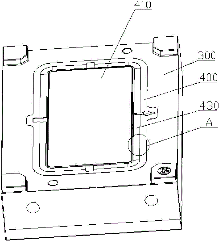
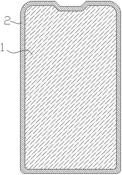
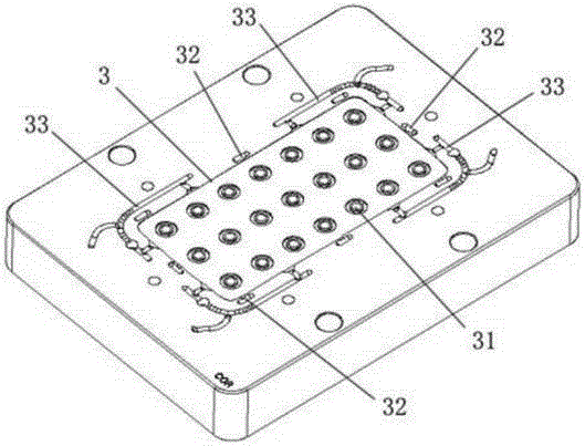
[0024] like Figure 3-6 As shown, the liquid silicone injection mold of this embodiment is a liquid silicone injection mold used to form a rubber edge structure on the side of the substrate, for example: to form a rubber edge on the side of the electronic product display glass, back shell and other substrates For waterproof, shockproof and dustproof. The injection mold includes a front template 100 , a front mold core 200 fixed in the front template, a rear template 300 , a rear mold core 400 fixed in the rear template, and a pouring sleeve 500 .

[0025] The rear mold core 400 is provided with a substrate fixing groove 410 , a pouring groove 420 and a glue overflow area 430 .

[0026] The substrate fixing groove is used to fix the substrate 001 with 410. After the substrate 001 is fixed, there is a predetermined interval between the side of the substrate 001 and the sid...


PUM

PropertyMeasurementUnit
depthaaaaaaaaaa
depthaaaaaaaaaa

Abstract

The invention discloses a liquid silicone rubber injection mold used for injection forming of a rubber edge structure at the side edge of a basal body. The liquid silicone rubber injection mold includes a front mold plate, a front mold core, a back mold plate, a back mold core and a pouring sleeve, and is characterized in that: the back mold core is provided with a basal body fixing groove, a rubber inlet groove communicated with the pouring sleeve, and a rubber overflow area; the basal body fixing groove is used for fixing the basal body, and a silicone rubber edge forming cavity is formed between the side edge of the basal body and the sidewall of the basal body fixing groove after the basal body is fixed and the mold is clamped; the rubber inlet groove is arranged along the sidewall of the basal body fixing groove; after mold clamping, a rubber inlet channel for communicating the rubber inlet groove and the silicone rubber edge forming cavity is formed between the top of the sidewall of the basal body fixing body and the front mold core; the rubber overflow area is arranged along one side, far away from the rubber edge forming cavity, of the rubber inlet groove, and is communicated with the rubber inlet groove through a rubber overflow channel; and the bottom of the rubber inlet channel is lower than the bottom of the rubber overflow channel. The liquid silicone rubber injection mold has the advantage of being good in injection effect and easy to control.

Description

technical field [0001] The invention relates to a liquid silicone injection mold. Background technique [0002] Publication No. 103516846A Chinese Invention Patent Document discloses a technology for making a waterproof and anti-collision silicone edge on the glass side. figure 1 Shown is the structure of the glass with silica gel edges disclosed by it, wherein 1 is glass, and 2 is the silica gel edge located at the periphery of the glass; figure 2 Shown is its disclosed injection mold, which is provided with a plurality of glue inlets around the molding cavity 3, and by adding runner grooves 33 to lead the glue to a plurality of glue inlets communicating with the molding cavity to reduce the Glue injection pressure; at the same time, an exhaust port 32 is set between the glue inlets to realize exhaust and avoid glue overflow, and the mold is also provided with a vacuum hole 31. This prior art can indeed reduce the pressure of glue injection to a certain extent, but still...

Claims


Application Information

Patent Timeline
Patent Type & Authority Patents(China)
IPC IPC(8): B29C45/26
CPCB29C45/2602B29C45/2616
Inventor 周永锋张绍华王长明谢守德
Owner DONGGUAN HUAQING OPTICAL TECH
Why Eureka
Try Eureka