
Power line carrier power utilization parameter receiving control device and method

A technology of power line carrier and power consumption parameters, which is applied in the direction of circuit devices, power network operating system integration, electrical components, etc., can solve the problem of uncoordinated power system and power users who cannot meet the requirements of peak load and valley filling control to achieve the best state. Issues such as the deprivation of the right to use electricity independently

Active Publication Date: 2014-10-01
STATE GRID CORP OF CHINA +1
View PDF3 Cites 7 Cited by
  • Summary
  • Abstract
  • Description
  • Claims
  • Application Information

AI Technical Summary

Problems solved by technology

Since the load control is remotely controlled by the power system, power users are deprived of their right to use electricity independently. In addition, simple load control does not coordinate the relationship between the power system and power users, and cannot meet the load control requirements for power grid load shifting. Best state

Method used


Image

  • Power line carrier power utilization parameter receiving control device and method
  • Power line carrier power utilization parameter receiving control device and method
  • Power line carrier power utilization parameter receiving control device and method

Examples


Embodiment Construction

[0044] In order to make the object, technical solution and advantages of the present invention more clear, the present invention will be further described in detail below in conjunction with the examples. It should be understood that the specific embodiments described here are only used to explain the present invention, not to limit the present invention.

[0045] The application principle of the present invention will be further described below in conjunction with the accompanying drawings and specific embodiments.

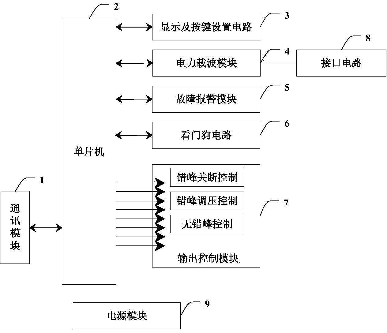
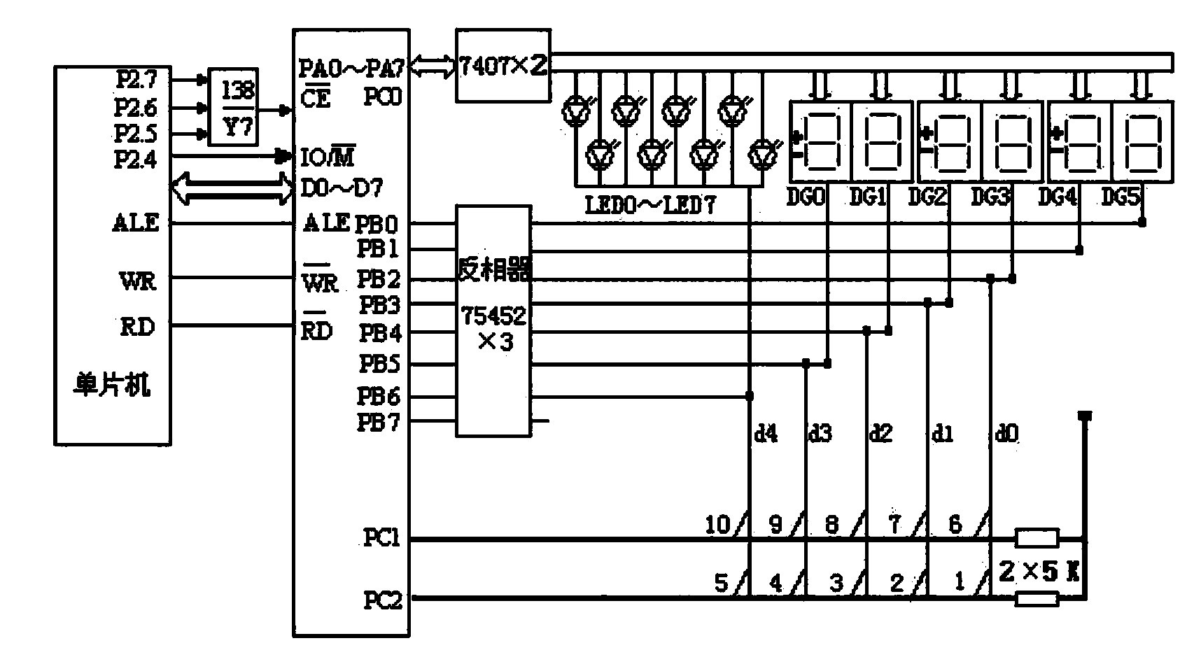
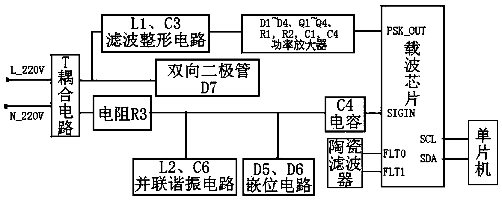
[0046] Such as figure 1 As shown, the power line carrier electric parameter reception control device of the embodiment of the present invention; the device hardware consists of a single chip microcomputer 2, a power supply module 9, a display and key setting circuit 3, a power carrier module 4, an interface circuit 8, a fault alarm module 5, and a communication module 1. The watchdog circuit 6 and the output control module 7 are composed.

[0047] The single ch...


PUM


Abstract

The invention discloses a power line carrier power utilization parameter receiving control device and method. A communication module, a single-chip microcomputer, a display and button setting circuit, a power line carrier module, a fault alarm device, a watchdog circuit and an output control module are arranged, power utilization information of an electric system is received in an electric line carrier communication mode, an electric power user sets a peak shifting control mode and parameters of a load according to the demands of the electric power user, different peak shifting control schemes are adopted according to different loads at different power utilization peak and valley time quantums, the periodical work time of power utilization equipment is reasonably controlled, and therefore peak shifting load control of power grid peak clipping and valley filling is achieved. The power line carrier power utilization parameter receiving control device is used for receiving power utilization information issued by an electric power system, and the peak shifting control mode and the power utilization parameters of the power utilization equipment are selected according to the willingness of the electric power user. The load control of power grid peak clipping and valley filling reaches the optimal state. The peak and valley load difference of running of a power grid is reduced, and the purposes of saving energy and reducing consumption are achieved.

Description

technical field [0001] The invention belongs to the technical field of power system information communication, and in particular relates to a device and method for receiving and controlling power parameters of a power line carrier. Background technique [0002] Currently known power line carrier controllers are mainly ones that use the power line as an information transmission channel to realize on-off control of electrical equipment. Patent application number CN102075013A proposes a method that utilizes power line The control method and device, wherein the intelligent load control device receives the load control command sent by the smart meter, and realizes the remote control on-off of the household electric load. Since the load control is remotely controlled by the power system, power users are deprived of their right to use electricity independently. In addition, simple load control does not coordinate the relationship between the power system and power users, and cannot...

Claims


Application Information

Patent Timeline
IPC IPC(8): H02J13/00H02J3/00H02J3/14
CPCY02B70/30Y02B70/3225Y04S20/222Y04S20/242
Inventor 於砚福
Owner STATE GRID CORP OF CHINA
Learn More