Linear two-way solenoid valve

A two-way solenoid valve, linear technology, applied in valve details, valve devices, multi-way valves, etc., can solve problems such as less than ideal control accuracy, high assembly process costs, and failure of the check valve core sealing function, and achieve assembly The process cost is relatively low, the assembly process cost is low, and the effect of easy and effective assembly

Active Publication Date: 2019-01-04
ZHEJIANG SANHUA COMMERCIAL REFRIGERATION CONTROLS CO LTD SHAOXING CITY
View PDF8 Cites 0 Cited by
  • Summary
  • Abstract
  • Description
  • Claims
  • Application Information

AI Technical Summary

Problems solved by technology

[0018] First, when the electromagnetic valve has a large flow demand, its valve port 1b will increase. Correspondingly, the stroke of the piston 30 needs to increase, and the stroke of the pilot valve head 50 needs to increase synchronously. Correspondingly, the stroke of the moving iron core 40 also needs to increase. However, with the increase of the stroke of the moving iron core 40, the suction force provided by the coil 70 decreases, and the valve opening ability of the valve body 1 drops sharply. In addition, the height of the solenoid valve will also increase; if the coil 70 increases , will bring a series of problems such as high power and temperature rise, and the volume of the solenoid valve will also increase
[0019] Second, during the two-way opening and closing process of the solenoid valve, the first check valve core 30a and the second check valve core 30c must always be aligned with the first piston flow channel 30k and the second piston flow channel 30d, so that radial Otherwise, the sealing function of the two check valve cores will fail, resulting in the failure of the two-way solenoid valve to close or open normally.
As a result, the structure of the pilot valve head 50 is relatively complicated, the processing is difficult, and the assembly process cost is relatively high. Even so, the control accuracy is still not ideal

Method used


Image

  • Linear two-way solenoid valve
  • Linear two-way solenoid valve
  • Linear two-way solenoid valve

Examples


Embodiment Construction

[0061] In order to enable those skilled in the art to better understand the technical solutions of the present invention, the present invention will be further described in detail below in conjunction with the accompanying drawings and specific embodiments.

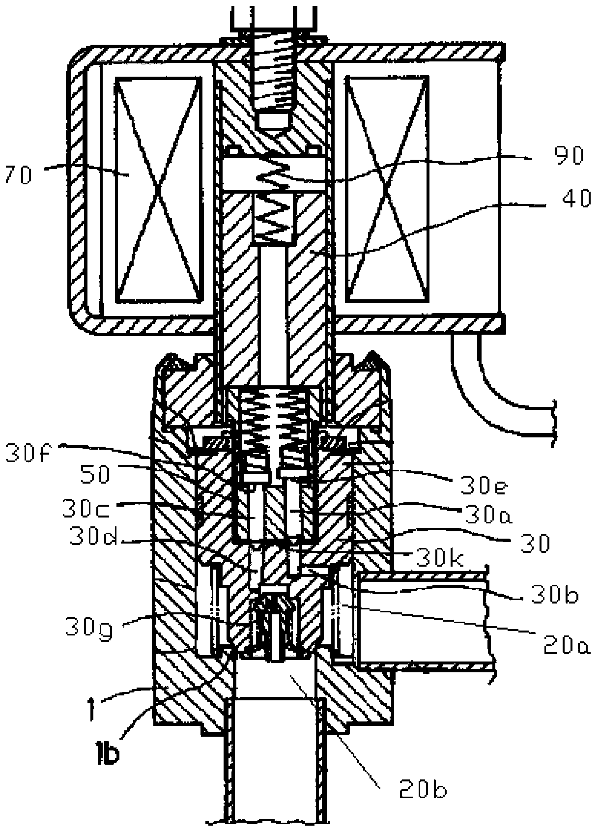
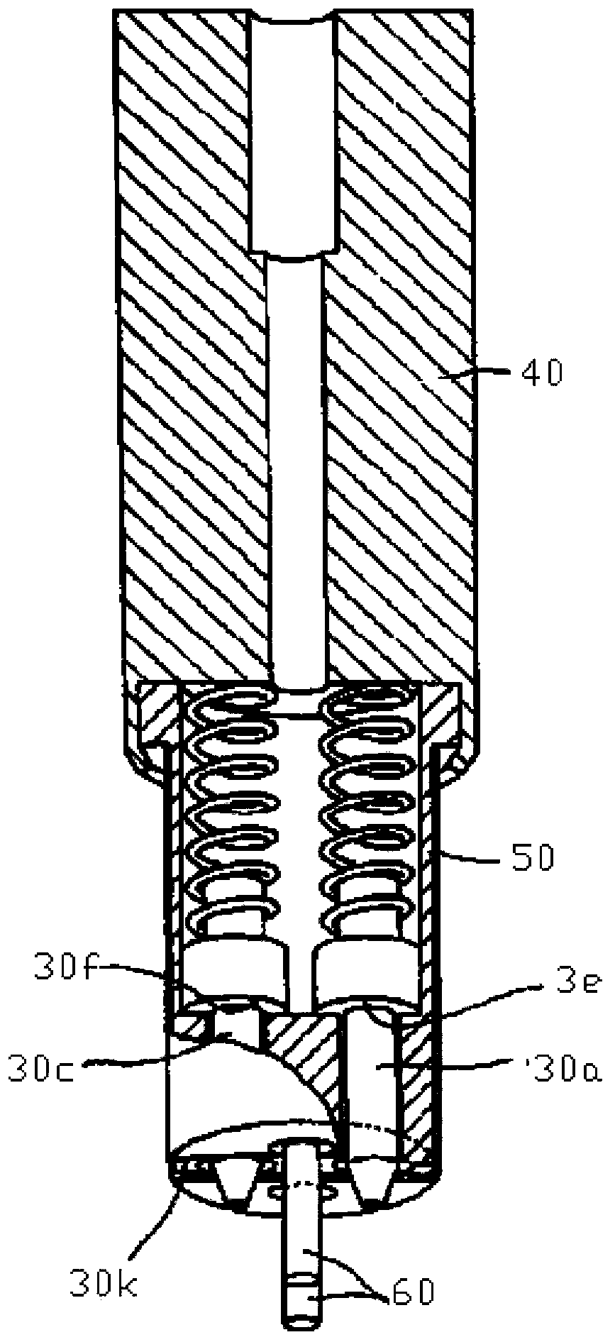
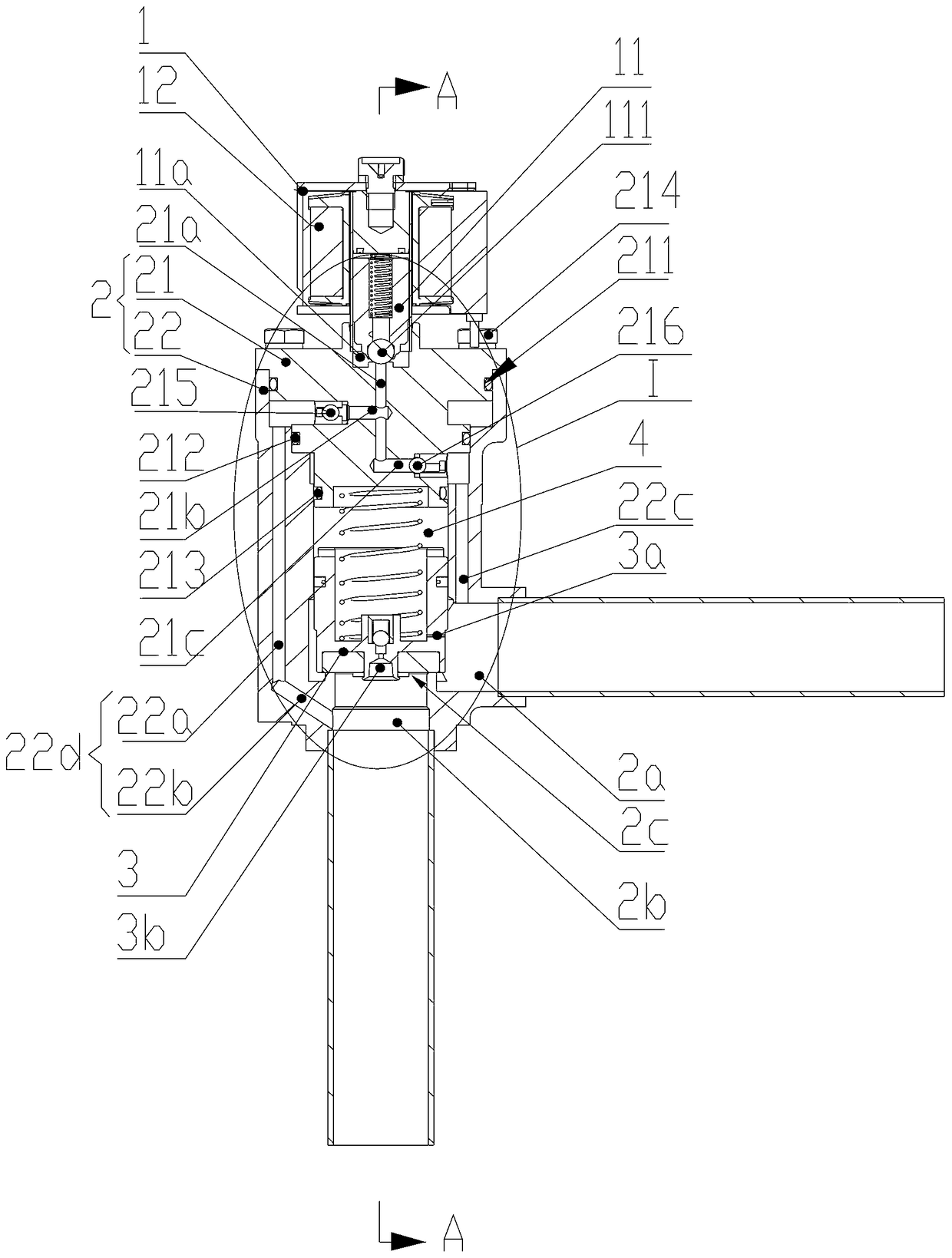
[0062] Please refer to Figure 3-8 , image 3 Axial sectional view of the first embodiment of the linear two-way solenoid valve provided for the invention; Figure 4 for image 3 Partial enlarged schematic diagram of part C in the middle; Figure 5 for image 3 A-A sectional view; Image 6 for image 3 Schematic diagram of the structure of the upper and middle valve body; Figure 7 for Figure 5 Schematic diagram of the structure of the upper and middle valve body; Figure 8 for image 3 The three-dimensional structure diagram of the upper and middle valve body.

[0063] The linear two-way solenoid valve has a main valve body 2 and a pilot valve body 11, and the main valve body 2 includes an upper valve body 21 ...


PUM


Abstract

The invention discloses a linear bidirectional electromagnetic valve. A piston is arranged in a valve cavity, a piston cavity is formed in the valve cavity, a first port and a second port whose connection and disconnection are controlled by the piston are arranged on a lower valve body, a first upper runner and a second upper runner communicated with the first port and the second port respectively are arranged in an upper valve body, a guide valve runner is arranged in the upper valve body to enable the piston cavity to be communicated with a guide valve port on a guide valve body through the guide valve runner, and a guide valve head of the guide valve body moves to open and close the guide valve port to connect or disconnect the first upper runner and the second upper runner with the piston cavity. Stroke of the piston and that of the guide valve head are separated, so that when the electromagnetic valve has great flow demand, valve opening capability of the valve body is unaffected, and expanding of a coil is not needed; the guide valve head and the upper valve body work in a matched manner, so that the electromagnetic valve is less prone to malposition; arranging of guide members which are troublesome on the upper valve body and the guide valve head is not needed, so that structure of the electromagnetic valve is simplified, and the electromagnetic valve is low in processing difficulty and assembly process cost.

Description

technical field [0001] The invention relates to the technical field of valve bodies, in particular to a linear two-way solenoid valve. Background technique [0002] General solenoid valves, due to structural limitations, can only flow and stop in one direction; in conventional systems, they often need to be used in conjunction with one-way valves. In the heat pump system, the flow direction of the refrigerant in the cooling and heating processes is opposite, and two single-way solenoid valves need to be installed in series to achieve bidirectional flow, resulting in a complex system structure, low reliability, and high cost. Therefore, it is necessary to Design a two-way solenoid valve. [0003] Please refer to Figure 1-2 , figure 1 It is a schematic diagram of a typical two-way solenoid valve structure, figure 2 for figure 1 Schematic diagram of the structure of the pilot valve head and moving iron core of the middle two-way solenoid valve. [0004] The two-way sol...

Claims


Application Information

Patent Timeline
Patent Type & Authority Patents(China)
IPC IPC(8): F16K11/24
CPCF16K11/24F16K27/00
Inventor 不公告发明人
Owner ZHEJIANG SANHUA COMMERCIAL REFRIGERATION CONTROLS CO LTD SHAOXING CITY
Why Eureka
Try Eureka