Scanning trigger control method and device of CT machine and CT machine

A scanning trigger and control method technology, applied in computer tomography scanners, echo tomography, etc., can solve problems such as errors and achieve the effect of speed error compensation

Active Publication Date: 2016-07-06
SIEMENS SHANGHAI MEDICAL EQUIP LTD
View PDF6 Cites 0 Cited by
  • Summary
  • Abstract
  • Description
  • Claims
  • Application Information

AI Technical Summary

Problems solved by technology

In practical applications, since the rotation speed of the rotating frame 12 may be different in different scanning periods, even the rotating speed of the rotating frame 12 may not be fixed in the same scanning period, so when using the corresponding virtual angle When sampling at a sampling time of α'=360° / MN, there are usually errors, so it is necessary to compensate for these errors

Method used


Image

  • Scanning trigger control method and device of CT machine and CT machine
  • Scanning trigger control method and device of CT machine and CT machine
  • Scanning trigger control method and device of CT machine and CT machine

Examples


Embodiment Construction

[0036] In order to make the purpose, technical solution and advantages of the present invention clearer, the following examples are given to further describe the present invention in detail.

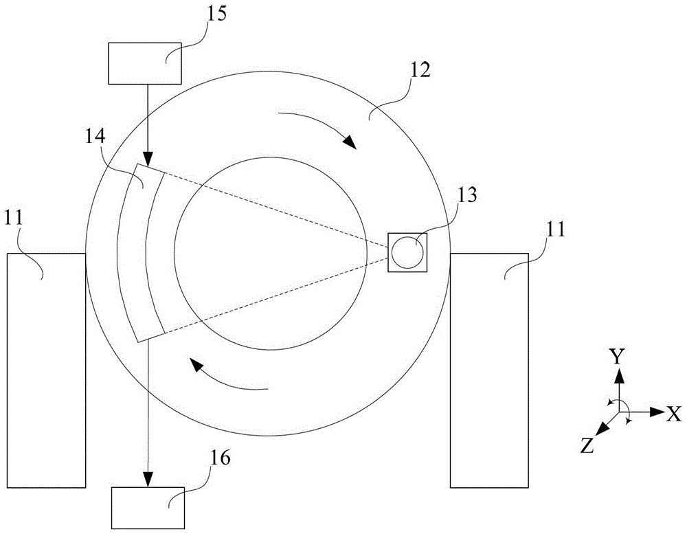
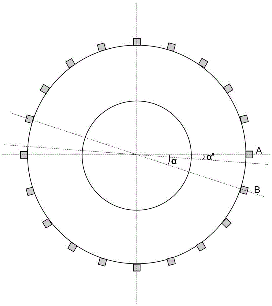
[0037] In the embodiment of the present invention, the rotation angle of one scanning cycle is also divided into M angle segments through M sensing elements evenly distributed on the rotating frame. These M sensing elements are only used as reference signals in the control process.

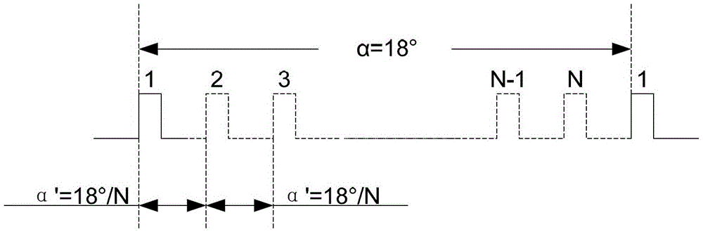
[0038] image 3 It is an exemplary flow chart of a scanning trigger control method of a CT machine in an embodiment of the present invention. Such as image 3 As shown, the method includes the following steps:

[0039] Step 301, predetermine the reference sampling period, and the reference rotation duration and reference sampling quantity corresponding to each angle segment.

[0040] In this step, if the mechanical installation errors of the M sensing elements are negligible, the angle of each angle segm...


PUM


Abstract

The invention provides a scanning trigger control method and device of a CT machine and a CT machine. Among them, the rotation angle of a scan cycle is divided into M angle segments; and the reference sampling period, and the reference rotation duration and reference sampling quantity corresponding to each angle segment are determined in advance; when performing a CT scan, start from the first angle segment At the beginning, for each angle segment, when the sensing signal at the beginning of the angle segment is received, the timing of the current rotation duration of this angle segment is started, and after delaying the sampling time corresponding to several samples, the corresponding sampling of this angle segment is started , when receiving the sensing signal at the end of the angle segment, the current rotation duration of the angle segment is obtained; the difference between the current rotation duration of the angle segment and the reference rotation duration is calculated, and the difference is passed through the angular segment The sampling time corresponding to several samples in the corresponding remaining sampling quantity is compensated. The technical scheme of the invention can compensate the speed error of the rotating frame.

Description

technical field [0001] The invention relates to the field of medical equipment, in particular to a scanning trigger control method and device for a computed tomography (CT) machine and a CT machine. Background technique [0002] As a kind of medical equipment, CT machine is widely used in the medical and health field to assist doctors in diagnosis. figure 1 A structural schematic diagram of a current CT machine is shown in . Such as figure 1 As shown, the CT machine includes: a bottom support component 11 , a rotating gantry (gantry) 12 , an X-ray tube 13 , an X-ray detector 14 , a control device 15 and an image reconstruction device 16 . [0003] Wherein, the rotating frame (gantry) 12 is generally a ring structure, and is installed on the bottom support member 11, and can rotate around its own axis. Usually, the direction parallel to the axis of the rotating frame 12 is called the Z direction, the horizontal direction perpendicular to the Z direction is called the X dir...

Claims


Application Information

Patent Timeline
Patent Type & Authority Patents(China)
IPC IPC(8): A61B6/03
Inventor 吕文刚
Owner SIEMENS SHANGHAI MEDICAL EQUIP LTD
Why Eureka
Try Eureka