
Ripple cancellation converter with high power factor

A power coefficient, converter technology, applied in output power conversion devices, DC power input to DC power output, high-efficiency power electronic conversion, etc., can solve the problems of flicker, high cost, and flicker getting worse.

Active Publication Date: 2014-09-17
QUEENS UNIV OF KINGSTON
View PDF2 Cites 5 Cited by
  • Summary
  • Abstract
  • Description
  • Claims
  • Application Information

AI Technical Summary

Problems solved by technology

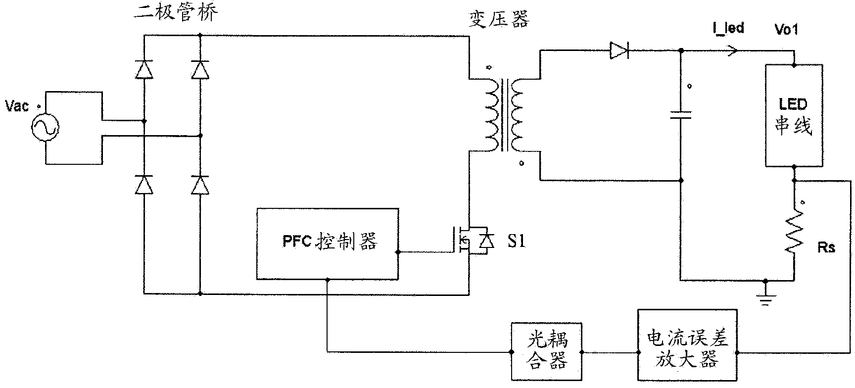
This presents several problems: First, as described above, for DC lighting (e.g., LED) applications, the pulsating current can cause visible flickering
In DC lighting applications, the flicker will get worse at reduced brightness
Third, the pulsating current will reduce the service life of many devices, for example, LED
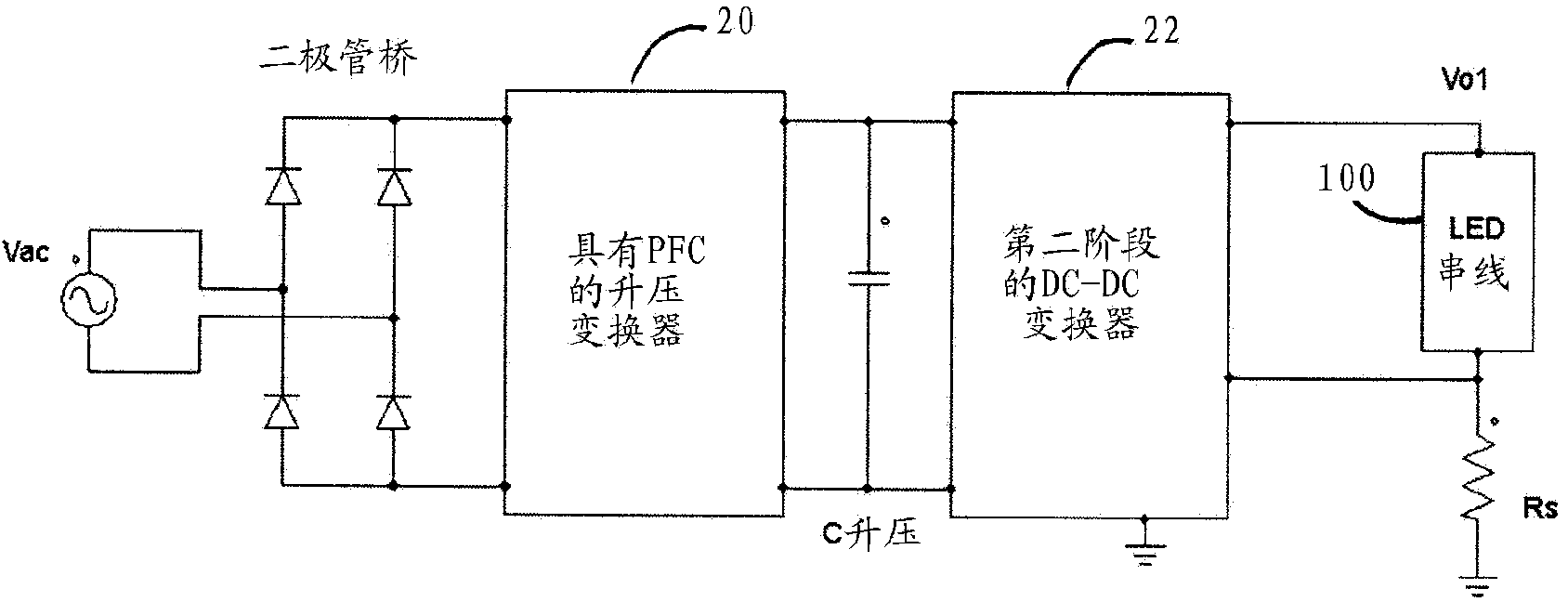
However, compared with the converter in Figure 1, the converter in Figure 2 has the disadvantages of requiring higher cost and larger size

Method used


Image

  • Ripple cancellation converter with high power factor
  • Ripple cancellation converter with high power factor
  • Ripple cancellation converter with high power factor

Examples


Embodiment

[0172] The methods and circuits described above can be applied to power supplies so that efficacy and current ripple reduction properties can be examined. in the attached Figure 23 A block diagram of the test setup is shown in , while Table 1 provides details of the equipment used. For this embodiment, a buck converter can be used as the ripple cancellation converter and an LED can be used as the load.

[0173] Table 1 Measuring equipment

[0174]

[0175] The added ripple cancellation converter substantially reduces the AC ripple in the output current. attached Figure 24 Shown is the measured ripple of the load current with an AC input of 120 volts, and the LED voltage is approximately 50 volts DC, and the DC current of the LED is approximately 0.7 amps DC. It is worth noting that the load current ripple is about 10 milliamps maximum to minimum, which is very small compared to a DC current of 0.7 amps. AC ripple in the main output (in the attached Figure 23 Medium...


PUM


Abstract

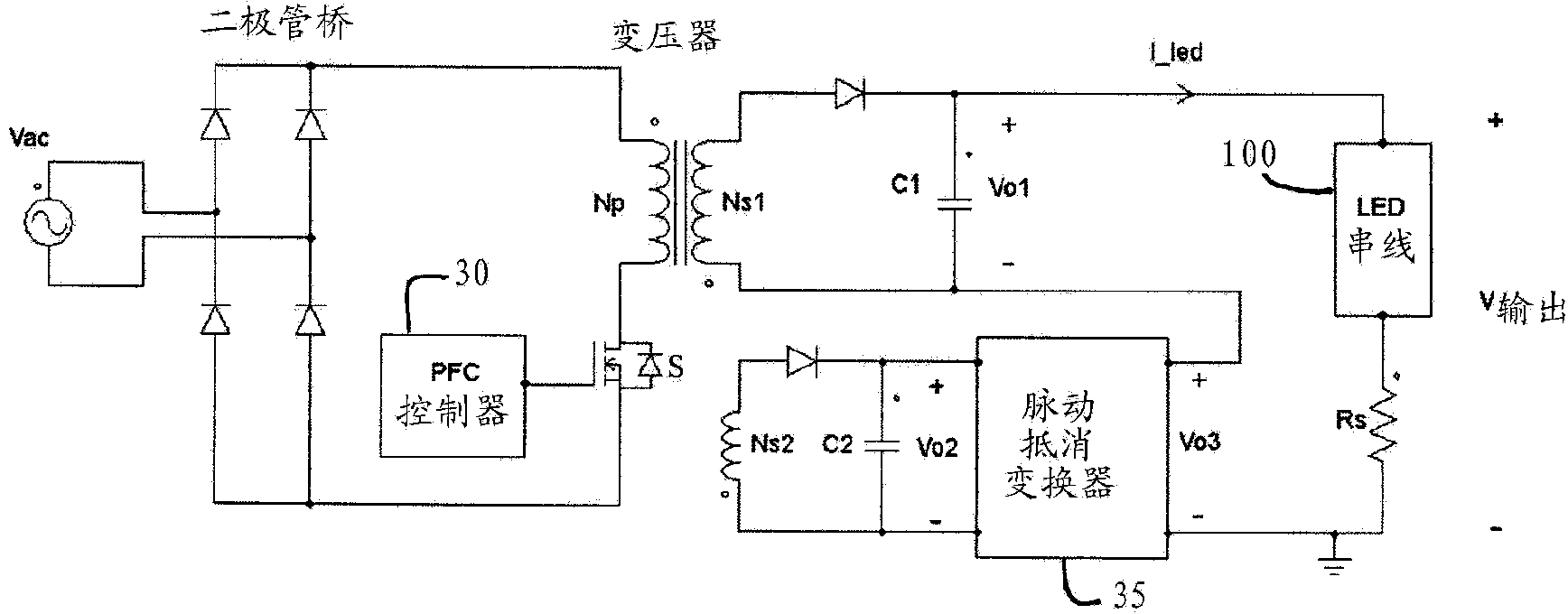
Provided are circuits and methods for use with a power supply that provides a main output including a main DC voltage having a first AC voltage ripple, or a main DC current having a first AC current ripple. A ripple cancellation converter provides a second AC voltage ripple connected in series with the main output, such that the first AC voltage ripple is substantially cancelled; or a second AC current ripple connected in parallel with the main output, such that the first AC current ripple is substantially cancelled. As a result, substantially ripple-free DC output power is provided.

Description

technical field [0001] The present invention relates to methods and circuits suitable for improving the conversion performance of AC and DC power supplies. In particular, methods and circuits are applicable to power supplies that can achieve high power factor (PF) on the AC side and, at the same time, reduce or substantially eliminate ripple on the DC output power side. The methods and circuits can be applied in a variety of different practices requiring high power coefficient and / or low output ripple. In particular, the methods and circuits may be suitable for DC lighting applications, such as light emitting diode (LED) lighting, where suppression of low frequency ripple in output power eliminates visible flicker. Background technique [0002] The problem of adjusting the current collection power coefficient correction for broadband equipment is becoming more and more urgent. For example, the latest regulation requires correction of power factor for any power supply with ...

Claims


Application Information

Patent Timeline
Patent Type & Authority Applications(China)
IPC IPC(8): H02J1/02H02M1/14H05B44/00
CPCH02M1/15H02M1/4258H05B33/0851H05B33/0815H02M1/143H02J1/02Y02B70/126H05B45/10H05B45/3725Y02B70/10H02M1/0009H02M1/08H02M1/14H02M1/42H02M3/33507
Inventor 刘雁飞
Owner QUEENS UNIV OF KINGSTON
Learn More