Wiring device between motor and controller

A wiring device and controller technology, which is applied in the direction of conductive connection, circuit, connection, etc., can solve the problems of damage to the MOS tube of the controller, easy loosening of the conductive ring, and threats to personal safety, so as to achieve clean wiring, avoid electric sparks, and improve The effect of safety performance

Active Publication Date: 2014-09-17
JIANGSU XIECHANG ELECTRONICS TECH
View PDF6 Cites 1 Cited by
  • Summary
  • Abstract
  • Description
  • Claims
  • Application Information

AI Technical Summary

Problems solved by technology

However, there are some problems in this wiring method; 1. Each phase line collides to generate electric sparks, resulting in damage to the MOS tube of the controller, which may indirectly cause the controller to catch fire and threaten personal safety; 2. The conductive ring is easily loosened by the clip and causes Poor contact

Method used


Image

  • Wiring device between motor and controller
  • Wiring device between motor and controller
  • Wiring device between motor and controller

Examples


Embodiment Construction

[0021] The present invention will be described in further detail below through specific examples.

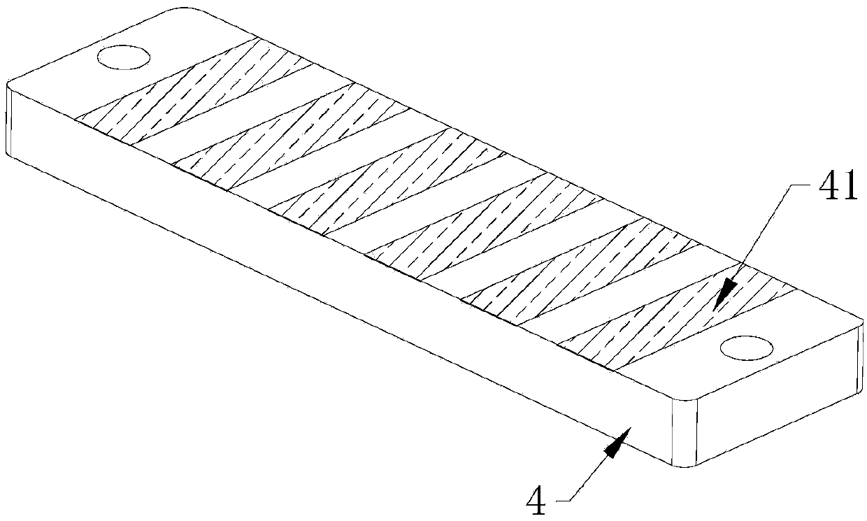
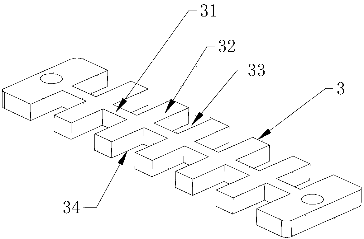
[0022] Such as Figures 1 to 6 As shown, a wiring device for a motor and a controller includes a base 4, a ball receiving plate 3, a spring mounting plate 2, and an upper pressure plate 1 made of insulating materials, the base 4, the ball receiving plate 3, and a spring mounting plate 2. The upper pressing plate 1 is installed and fixed sequentially from bottom to top. The ball receiving plate 3 includes a plurality of placement grooves 34 for accommodating the balls 6, and a number of pressing grooves 33 that are equal in number to the placement grooves 34 and correspond one-to-one. The wire groove 33 and the placement groove 34 are all independent, and the ball receiving plate 3 includes a central skeleton rod 31 and several groove rods 32 arranged in parallel on both sides of the central skeleton rod 31, and the distance between each groove rod 32 constitutes the Describe th...


PUM


Abstract

The invention discloses a wiring device between a motor and a controller. The wiring device comprises a base, a roll ball containing board, a spring mounting plate and a top board, wherein the base, the roll ball containing board, the spring mounting plate and the top board are made of insulating materials. The roll ball containing board comprises a plurality of mounting grooves and wire pressing grooves, wherein the mounting grooves are used for containing roll balls, the wire pressing grooves correspond to the mounting grooves in a one-to-one mode, and the wire pressing grooves and the mounting grooves are all independent. A baseplate is provided with conductive structures which make the mounting grooves and the wire pressing grooves be communicated in a one-to-one mode. The spring mounting plate comprises a plurality of spring mounting holes and a plurality of wire pressing holes, wherein the spring mounting holes correspond to the mounting grooves in position in a one-to-one mode, and the wire pressing holes correspond to the wire pressing grooves in position in a one-to-one mode. The roll balls are mounted in all the mounting grooves. Springs for pressing the roll balls are mounted in the spring mounting holes respectively. The top board presses the springs and is provided with bolt holes which correspond to the wire pressing holes in position in a one-to-one mode. Wire pressing bolts are mounted in all the bolt holes and all the wire pressing holes. According to the wiring device, the motor and the controller are wired quickly, the wiring part is firm, all phases of wires will not be collided, and the wiring part is neat.

Description

technical field [0001] The invention relates to a wiring device, in particular to a wiring device for a motor and a controller. Background technique [0002] In the field of motor wiring of electric vehicles, there are multiple wires connecting the motor and the controller. At present, the wire ends of the conventional controller and the motor generally have a conductive ring, and the clip is used to clamp the conductive ring to make the controller The wires are connected to the wires of the motor. However, there are some problems in this wiring method; 1. Each phase line collides to generate electric sparks, resulting in damage to the MOS tube of the controller, which may indirectly cause the controller to catch fire and threaten personal safety; 2. The conductive ring is easily loosened by the clip and causes Poor contact. Contents of the invention [0003] The technical problem to be solved by the present invention is: to provide a wiring device for the motor and the ...

Claims


Application Information

Patent Timeline
Patent Type & Authority Applications(China)
IPC IPC(8): H01R9/00H01R9/22H01R4/52H01R4/36
Inventor 顾挺
Owner JIANGSU XIECHANG ELECTRONICS TECH
Why Eureka
Try Eureka