
A rake tooth type biomass material conveying device

A conveying device and biomass technology, applied in the field of machinery, can solve problems such as low efficiency, large manpower, and large floor space, and achieve the effects of reducing the number of installations, saving construction costs, and reducing losses

Active Publication Date: 2016-08-24
CHINA CAMC ENG
View PDF13 Cites 0 Cited by
  • Summary
  • Abstract
  • Description
  • Claims
  • Application Information

AI Technical Summary

Problems solved by technology

[0006] This application provides a rake-tooth biomass material conveying device to solve the problems of large floor area and consumption of a large amount of manpower and material resources during the construction of belt conveyors; and the problems of poor conveying capacity and low efficiency of belt conveyors

Method used


Image

  • A rake tooth type biomass material conveying device
  • A rake tooth type biomass material conveying device
  • A rake tooth type biomass material conveying device

Examples


Embodiment 2

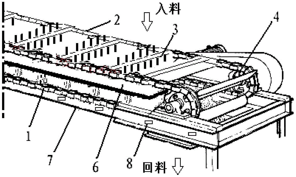
[0089] In combination with the above-mentioned embodiments, a specific example is used to illustrate the working process of a rake-tooth biomass material conveying device. The specific workflow can be as follows:

[0090] S1. The feeding belt corridor adds biomass materials to the intermediate partition 6 .

[0091] S2. The driving device provides power to the drive shaft 4, and the drive shaft 4 drives the first traction chain 1, the second traction chain 2 and the transmission shaft 5 to rotate. The rake teeth 3 fixed on the first traction chain 1 and the second traction chain 2 move the biomass material on the intermediate partition 6 along with the movement of the first traction chain 1 and the second traction chain 2 .

[0092] S3. The biomass material moving to the top of the intermediate partition 6 falls on the lower bottom plate 7 .

[0093] S4. The rake teeth 3 push the biomass materials falling on the lower bottom plate 7 to move (the movement direction of the rak...


PUM


Abstract

The application provides a rake tooth type biomass material conveying device, including: a first traction chain, a second traction chain, a rake tooth, a drive shaft, a transmission shaft, an intermediate partition, a lower bottom plate, a feeding port and a spiral tensioning device; the driving shaft and the transmission shaft are arranged symmetrically; the helical tensioning device is connected with the driving shaft to control the tension of the first traction chain and / or the second traction chain; the The first traction chain is respectively engaged with the drive shaft and the transmission shaft; the second traction chain is arranged symmetrically with the first traction chain, and the second traction chain is respectively connected with the drive shaft and the transmission shaft. The transmission shaft is meshed; so that the drive shaft drives the first traction chain and the second traction chain to perform chain transmission around the transmission shaft. The application solves the problems that the belt conveyor occupies a large area and consumes a lot of manpower and material resources; and the belt conveyor has poor conveying capacity and low efficiency during construction.

Description

technical field [0001] The present application relates to the field of mechanical technology, in particular to a rake tooth type biomass material conveying device. Background technique [0002] Conveyors are usually required in front of the boilers of paper mills, sugar factories and biomass power plants to transport biomass materials to the furnace. For example, biomass materials such as bagasse, straw, bark or wood chips are transported to the furnace by conveyors. [0003] Generally, belt conveyors are usually used to transport biomass materials. Structural reference of belt conveyor figure 1 , shows a schematic structural view of a belt conveyor. The biomass material enters the belt conveyor from one end (feeding belt corridor), and the excess material after the biomass material enters the furnace is discharged from the other end (return belt corridor). [0004] However, the above-mentioned belt conveyor has the following problems when transporting materials: since t...

Claims


Application Information

Patent Timeline
Patent Type & Authority Patents(China)
IPC IPC(8): B65G19/04B65G19/18
Inventor 洪浩胡伟周军宏黄斌许世勇刘新明李璐张雷刘超孙建山
Owner CHINA CAMC ENG
Learn More