Flow Switch

A flow switch and flow technology, applied in the direction of electrical switches, electrical components, circuits, etc., can solve the problems of flow switch damage, switch body mobility damage, etc., to reduce sensitivity, reduce the risk of deposition, and reduce the risk of deposition. sporty effects

Active Publication Date: 2014-09-10
ALFRED KARCHER GMBH & CO KG
View PDF8 Cites 3 Cited by
  • Summary
  • Abstract
  • Description
  • Claims
  • Application Information

AI Technical Summary

Problems solved by technology

Damage to the flow switch due to entrained dirt particles, especially if entrained by the fluid can impair the movability of the switch body

Method used


Image

  • Flow Switch
  • Flow Switch

Examples


Embodiment Construction

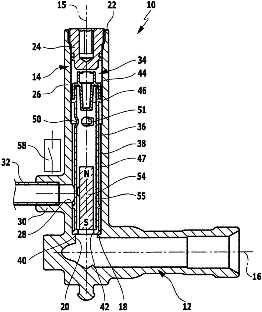
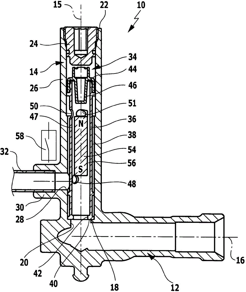
[0026] A preferred embodiment of a flow switch according to the invention, designated as a whole by the reference numeral 10 , is shown schematically in its use position in the drawing. The flow switch comprises an input line 12 configured as a horizontally oriented tube, to which a vertically oriented outer tube 14 is coupled, the longitudinal axis 15 of which is oriented perpendicularly to the longitudinal axis 16 of the input line. In the transition region between the supply line 12 and the outer tube 14 , the outer tube 14 defines a first outer tube end side 18 which has a fluid inlet 20 through which, for example, a pump of a high-pressure cleaner places the Fluid under pressure can flow into the outer tube 14 . The second outer tube end side 22 facing away from the supply line 12 is closed by a plug 24 which can be screwed into the outer tube 14 .

[0027] Between the first outer tube end side 18 and the second outer tube end side 22 extends a cylindrical outer tube cir...


PUM


Abstract

The invention relates to a flow switch (10) comprising a flow channel (34) which has a liquid inlet (20) and a liquid outlet (28), through which a liquid can flow, and in which a permanently-magnetised switching body (54) is arranged that is able to be displaced, by the liquid, as a function of the flow, said switch also comprising a switching element (58) that can be magnetically actuated depending on the position of said switching body. In order to improve the flow switch (10) such that it is less sensitive to dirt particles carried along by the liquid, the invention suggests that an inner pipe (36) surrounded by an annular space (38) is arranged in the flow channel (34), receives said displaceable switching body (54), and has an inflow opening (42) fluidically connected to the liquid inlet (20), as well as at least one first and at least one second outflow opening (48, 50, 51), wherein said at least one second outflow opening (50, 51) is axially offset to the at least one first outflow opening (48) and said outflow openings open into the annular space (38). The annular space (38) is fluidically connected to the liquid outlet (28).

Description

technical field [0001] The invention relates to a flow switch with a flow channel through which a fluid can flow and a switching element which can be magnetically actuated depending on the position of the switch body, the flow channel has a fluid inlet and a fluid outlet, and in the flow A flow-dependent, permanently magnetized switching body displaceable by the fluid is arranged in the channel. Background technique [0002] Such flow switches are used, for example, in heated high-pressure cleaners, in which a fluid, preferably water, can be brought under pressure by means of a pump and subsequently heated by means of a heat exchanger. To ensure that the heat exchanger only starts to operate when the pump is delivering fluid to it, a flow switch of the type mentioned at the beginning of this article is inserted in the flow connection between the pump and the heat exchanger. The flow switch has a flow channel through which fluid brought under pressure by the pump can flow. ...

Claims


Application Information

Patent Timeline
Patent Type & Authority Applications(China)
IPC IPC(8): H01H35/40
CPCH01H35/405
Inventor 迈克尔·博姆塞巴斯蒂安·特劳特斯特凡·埃尔哈特罗尔夫·弗里德里希
Owner ALFRED KARCHER GMBH & CO KG
Why Eureka
Try Eureka