A switching circuit and electronic equipment

A technology for switching circuits and electronic equipment, applied in the field of electronics, can solve the problems that the main chip’s working voltage cannot be guaranteed, and the reliability of image processing can be reduced.

Active Publication Date: 2017-10-17
HUAWEI TECH CO LTD
View PDF3 Cites 0 Cited by
  • Summary
  • Abstract
  • Description
  • Claims
  • Application Information

AI Technical Summary

Problems solved by technology

[0004] In the above-mentioned process of realizing the voltage conversion of the interface level between the image sensor chip and the main chip, during the process of transmitting from the image sensor board to the core board, due to the current on the connection line between the image sensor board and the core board Larger, then the voltage received by the core board has attenuation. When the voltage attenuation is too large, the working voltage of the main chip cannot be guaranteed, which in turn reduces the reliability of image processing.

Method used


Image

  • A switching circuit and electronic equipment
  • A switching circuit and electronic equipment
  • A switching circuit and electronic equipment

Examples


Embodiment Construction

[0028] The following will clearly and completely describe the technical solutions in the embodiments of the present invention with reference to the accompanying drawings in the embodiments of the present invention. Obviously, the described embodiments are only some, not all, embodiments of the present invention. Based on the embodiments of the present invention, all other embodiments obtained by persons of ordinary skill in the art without creative efforts fall within the protection scope of the present invention.

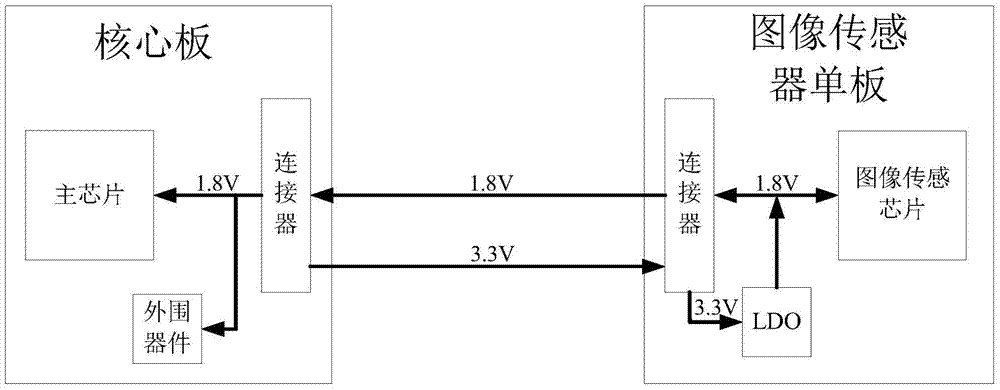
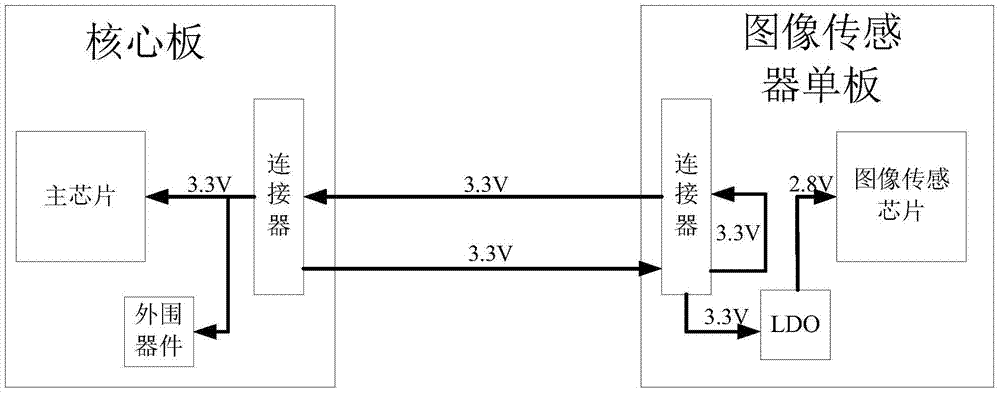
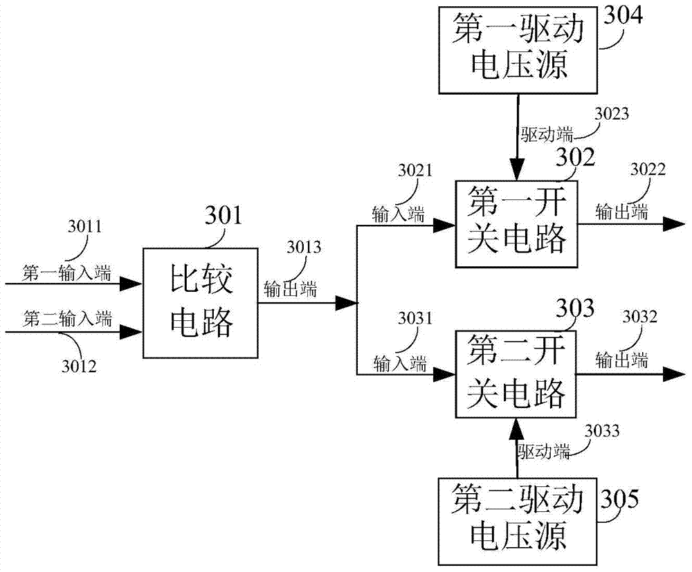
[0029] The embodiment of the present invention provides a switching circuit, such as image 3 As shown, it includes: a comparison circuit 301 , a first switch circuit 302 , a second switch circuit 303 , a first driving voltage source 304 and a second driving voltage source 305 .

[0030] Wherein, the comparison circuit 301 includes: a first input terminal 3011 , a second input terminal 3012 and an output terminal 3013 . The first switch circuit 302 includes: an inpu...


PUM


Abstract

The invention provides a switching circuit and electronic equipment, relates to the field of electronic technology, and is used for improving the reliability of image processing. The switch circuit includes: a comparison circuit, a first switch circuit, a second switch circuit, a first drive voltage source and a second drive voltage source; the two input terminals of the comparison circuit respectively receive the input voltage and the reference voltage, and the output terminals are respectively connected to the first switch The input end of the circuit is connected to the input end of the second switch circuit; the driving end of the first switching circuit is connected to the first driving voltage source; the driving end of the second switching circuit is connected to the second driving voltage source; the comparison circuit determines whether the input voltage is greater than the reference voltage, When it is determined that the input voltage is greater than the reference voltage, it outputs a high level, otherwise it outputs a low level; when the comparison circuit outputs a high level, the second switch circuit is disconnected, the first switch circuit is turned on and outputs the first driving voltage; when the comparison circuit When outputting low level, the first switch circuit is turned off, the second switch circuit is turned on and outputs the first driving voltage.

Description

technical field [0001] The invention relates to the field of electronic technology, in particular to a switching circuit and electronic equipment. Background technique [0002] The image sensor is an important part of the camera. It is generally composed of an image sensor single board containing an image sensor chip and a core board containing the main chip. At present, the interface level voltages of most image sensor chips are 1.8V and 2.8V, and the interface level voltages of the main chip are 1.8V and 3.3V. Since the voltage of the interface level is different, it is necessary to convert the voltage of the interface level between the image sensor chip and the main chip. [0003] The prior art provides a method for realizing the voltage conversion of the interface level between the image sensor chip and the main chip. The voltage conversion method defines several pins on the connector between the core board and the image sensor single board. , when the interface level ...

Claims


Application Information

Patent Timeline
Patent Type & Authority Patents(China)
IPC IPC(8): H03K19/0185
CPCH03K5/24H03K19/017527H04N23/66H04N25/00
Inventor 尹巍
Owner HUAWEI TECH CO LTD
Why Eureka
Try Eureka