Input adaptive self-excited zeta converter

A self-adaptive, converter technology, which is applied in the direction of converting DC power input into DC power output, output power conversion devices, instruments, etc., to achieve the effect of reducing freewheeling conduction loss and small current detection loss

Active Publication Date: 2016-04-20
沈阳钢中宝科技有限公司
View PDF5 Cites 2 Cited by
  • Summary
  • Abstract
  • Description
  • Claims
  • Application Information

AI Technical Summary

Problems solved by technology

[0003] The technical problem to be solved by the present invention is to provide a current-limiting converter with input self-adaptive for the deficiencies of existing self-excited Zeta converters in terms of current detection loss, current-limiting protection capability of important devices, freewheeling conduction loss, etc. Input Adaptive Self-excited Zeta Converter with Small Protection Capability, Current Sensing Loss and Freewheeling Conduction Loss

Method used


Image

  • Input adaptive self-excited zeta converter
  • Input adaptive self-excited zeta converter
  • Input adaptive self-excited zeta converter

Examples


Embodiment 1

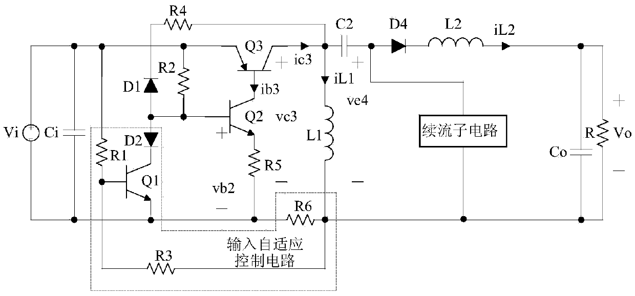
[0034] refer to image 3 , Embodiment 1 includes a main circuit and an input adaptive control circuit for adaptive current limiting protection, the main circuit includes an input capacitor Ci, a PNP type BJT transistor Q3, a capacitor C2, a diode D4, an inductor L1, an inductor L2, an output The capacitor Co, the freewheeling sub-circuit for reducing the freewheeling conduction loss and the driving circuit for driving the PNP type BJT transistor Q3. The drive circuit includes NPN type BJT tube Q2, resistor R2, resistor R4, capacitor C5, resistor R5, diode D3 and diode D1; the input adaptive control circuit includes NPN type BJT tube Q1, diode D2, resistor R1, resistor R3, resistor R6 and capacitor C1; the freewheeling sub-circuit includes a PNP type BJT tube Q5, an NPN type BJT tube Q4, a resistor R7, a resistor R9, a resistor R8, a resistor R10, a capacitor C3 and a capacitor C4. The role of diode D3 and capacitor C5 is to improve the switching speed of NPN type BJT tube Q2,...

Embodiment 2

[0043] refer to Figure 6 , Embodiment 2 On the basis of Embodiment 1, the diode D3 is omitted, and the diode D3 is replaced by a Zener tube Z. The cathode of the Zener tube Z is connected to the base of the NPN type BJT tube Q2, and the anode of the Zener tube Z is connected to the DC The negative terminal of the voltage source Vi is connected, and the voltage regulator tube Z has the function of widening the working range of the circuit.

[0044] refer to Figure 7-Figure 8 , The working principle of the circuit of embodiment 2 is similar to that of embodiment 1, and also has an input adaptive current limiting function. In a steady-state working cycle (t21 to t23), the working state of embodiment 2 in the mode of critical continuous inductor current iL1 and intermittent inductor current iL2 can be roughly divided into two stages: t21 to t22 and t22 to t23. The main difference lies in: when the embodiment 2 is in the period from t21 to t22, the base voltage vb2 of Q2 is equ...


PUM


Abstract

The invention relates to an input adaptive auto-excitation type Zeta converter. The input adaptive auto-excitation type Zeta converter comprises a main loop and an input adaptive control circuit which is used for adaptive current limit protection; the main loop comprises an input capacitor Ci, a PNP type BJT tube Q3, a capacitor C2, a diode D4, an inductor L1, an inductor L2, an output capacitor Co, a flywheel sub-circuit used for lowering the follow current conduction consumption and a drive circuit used for driving the PNP type BJT tube Q3; the drive circuit comprises an NPN type BJT tube Q2, a resistor R2, a resistor R4, a resistor R5 and a diode D1, and the input adaptive control circuit comprises an NPN type BJT tube Q1, a diode D2, a resistor R1, a resistor R3 and a resistor R6. According to the input adaptive auto-excitation type Zeta converter, the input adaptive control circuit controls the current of the inductor L1 or the collecting electrode current of the PNP type BJT tube Q3 and has a current limit function with the input adaptive characteristic, and moreover, the input adaptive control circuit also realizes smaller current detection consumption; the flywheel sub-circuit enables the follow current conduction consumption of the Zeta converter to be lowered.

Description

technical field [0001] The invention relates to the technical field of self-excited DC-DC converters, in particular to an input adaptive self-excited Zeta converter. Background technique [0002] Chinese patent ZL201210154791.4 discloses a "BJT type self-excited Zeta converter with small driving loss of the main switching tube", such as figure 1 As shown, it includes the main loop composed of input capacitor Ci, PNP type BJT tube Q1, capacitor C, inductor L1, inductor L2, diode D, diode D1 and capacitor Co, and consists of resistor R1, resistor R2, resistor R3, resistor R4, The driving unit of the main switching tube Q1 composed of capacitor C1, NPN type BJT tube Q2 and PNP type BJT tube Q3 also includes a current circuit composed of resistor R5, resistor R6, resistor R7, capacitor C2, diode D2 and NPN type BJT tube Q4 feedback branch. This kind of Zeta converter has a positive polarity buck-boost voltage conversion function, the circuit structure is simple, and the number...

Claims


Application Information

Patent Timeline
Patent Type & Authority Patents(China)
IPC IPC(8): H02M3/155
Inventor 陈怡顾伟驷南余荣
Owner 沈阳钢中宝科技有限公司
Why Eureka
Try Eureka