Vertical oil storage device for transformer

A transformer and vertical technology, applied in the field of vertical oil storage equipment for transformers, can solve the problems affecting the normal expansion and contraction of metal bellows, affecting the normal operation of the transformer, etc. low effect

Inactive Publication Date: 2014-09-10
SHUANGLIU COUNTY POWER SUPPLY BRANCH STATE GRID SICHUAN ELECTRIC POWER
View PDF8 Cites 1 Cited by
  • Summary
  • Abstract
  • Description
  • Claims
  • Application Information

AI Technical Summary

Problems solved by technology

When the existing external oil-type metal bellows type oil storage equipment is used, the moisture carried by the moisture entering the respirator will be deposited in the metal bellows, and too much water deposited in the metal bellows will affect the normal expansion and contraction of the metal bellows. This will affect the normal operation of the transformer

Method used


Image

  • Vertical oil storage device for transformer

Examples


Embodiment 1

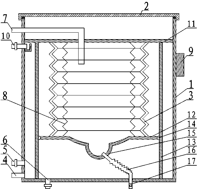
[0016] Such as figure 1 As shown, the vertical oil storage equipment for transformers includes a housing 1, a cover 2, a metal bellows 3, an elastic expansion member 8, an oil level gauge 9 and a drain pipe 16, wherein the housing 1 constitutes a barrel with an open upper end shape, the cover 2 is connected with the housing 1 and closes the upper opening of the housing 1 , and the oil level gauge 9 is arranged on the housing 1 . The metal bellows 3 is vertically arranged in the housing 1, the upper end of the metal bellows 3 is connected with an upper connecting plate 11 closing its upper opening, the lower end of the metal bellows 3 is connected with a lower connecting plate 12 closing its lower opening, and the upper connecting plate 11 Periphery is sealed and fixed on the inner wall of the housing 1. The central part of the lower connecting plate 12 is concave to form a water storage tank 15. The water storage tank 15 opens upward and is hemispherical in shape. One end of t...

Embodiment 2

[0019] This embodiment makes the following further limitations on the basis of Embodiment 1: the lower connecting plate 12 of this embodiment is formed with a cylindrical transition section with a large upper part and a smaller lower part, wherein the cylindrical transitional section is defined by the water tank 15 The edge spreads to the water tank 15 peripheral areas. In this embodiment, under the transition action of the cylindrical transition section, it is possible to avoid loud noises when the water in the metal bellows 3 flows to the water storage tank 15 .

Embodiment 3

[0021] In order to prevent the metal bellows 3 from shifting, twisting or deforming when it expands and contracts, this embodiment makes the following further limitations on the basis of Embodiment 1 or Embodiment 2: This embodiment also includes a plurality of vertically arranged guide rails 13 , wherein, the upper and lower ends of the guide rail 13 are respectively connected with the lower end surface of the upper connecting plate 11 and the upper end surface of the lower connecting plate 12, and the lower connecting plate 12 is connected with the rollers 14 embedded in the guide rail 13 which are equivalent in number and position one-to-one with the guide rail 13.


PUM


Abstract

The invention discloses a vertical oil storage device for a transformer. The vertical oil storage device comprises a housing, a seal cover, a metal bellows, an elastic telescopic member and a drain pipe. The seal cover is connected with the housing and closes an upper opening of the housing; the metal bellows is disposed inside the housing; the upper and lower ends of the metal bellows are connected with an upper connecting board and a lower connecting board; the center of the lower connecting board recesses down to form a water accumulation recess in a hemispheric shape; the inside of the water accumulation recess is communicated with the outside through the drain pipe; a center segment of the drain pipe is in a bellows shape; the elastic telescopic member is disposed inside the metal bellows; the upper and lower ends of the elastic telescopic member are connected with the upper and lower connecting boards respectively; the housing, the metal bellows, the upper connecting board and the lower connecting board form an oil storage chamber; an oil transfer pipe, an oil injection pipe and a blow-down pipe which are communicated with the oil storage chamber are arranged on the housing. The vertical oil storage device has the advantages that water inside the metal bellows can be discharged automatically, the metal bellows can normally telescope under the protection of the elastic telescopic member, and accordingly normal operation of the vertical oil storage device can be ensured.

Description

technical field [0001] The invention relates to the field of transformer protection, in particular to vertical oil storage equipment for transformers. Background technique [0002] With the development of information society, people's dependence on electricity has been greatly increased, and the quality requirements for power supply equipment are becoming more and more stringent. As an important equipment in the power distribution system, the oil-immersed transformer is an important guarantee for various production activities to ensure its normal operation. The existing oil-immersed transformers are usually equipped with oil storage equipment as a safety component. Among the oil storage equipment of many oil-immersed transformers, the external oil-type metal bellows type oil storage equipment is widely used, and the external oil-type metal bellows type oil storage equipment is widely used. The oil equipment is to install a metal bellows in the oil storage equipment, and the...

Claims


Application Information

Patent Timeline
IPC IPC(8): H01F27/14
Inventor 王杰
Owner SHUANGLIU COUNTY POWER SUPPLY BRANCH STATE GRID SICHUAN ELECTRIC POWER
Why Eureka
Try Eureka