Method of Measuring Phase Difference of Bohr Resonance with Digital Oscilloscope

A digital oscilloscope and Boer resonance technology, applied in the field of physical experimental parameter measurement, can solve the problems of reduced flash, insufficient partial pressure of experimental instruments, abnormal working state of electronic circuits of measuring instruments, etc., to avoid influence and expand thinking ability.

Inactive Publication Date: 2016-08-31
SICHUAN UNIV
View PDF5 Cites 0 Cited by
  • Summary
  • Abstract
  • Description
  • Claims
  • Application Information

AI Technical Summary

Problems solved by technology

[0007] Due to the high current of the flash lamp, the internal partial voltage of the experimental instrument is insufficient when the flash lamp is used, which may cause abnormal working status of the electronic circuit of the measuring instrument. It has been found in the experiment that the displayed cycle data has abnormal changes, usually when the flash occurs. The significant reduction has caused many students to question: Is the phase difference data accurate?

Method used


Image

  • Method of Measuring Phase Difference of Bohr Resonance with Digital Oscilloscope
  • Method of Measuring Phase Difference of Bohr Resonance with Digital Oscilloscope

Examples


Embodiment Construction

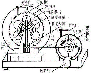
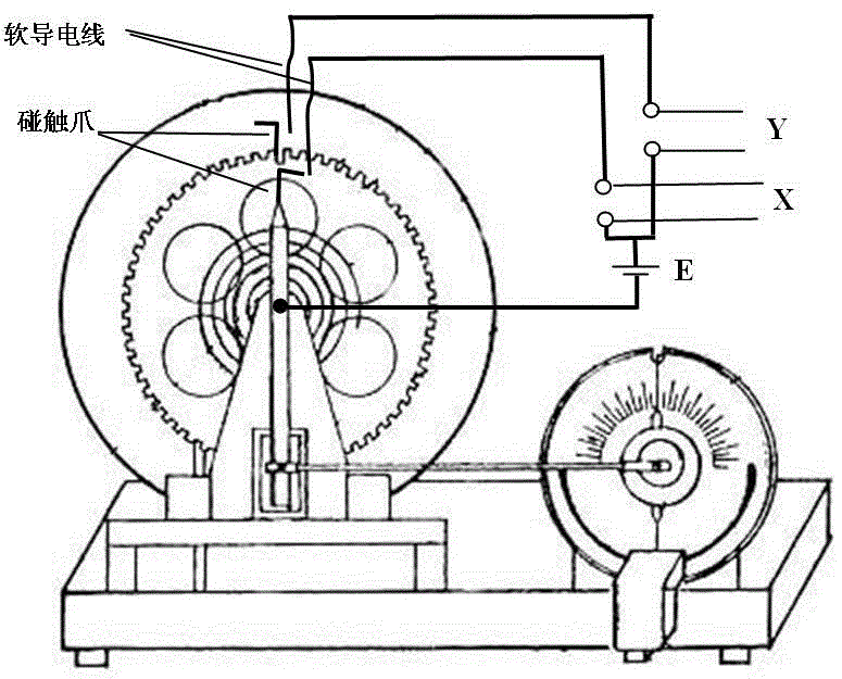
[0012] The method for measuring the phase difference of Bohr resonance with a digital oscilloscope, the steps are:

[0013] Step 1: The balance wheel and rocker of the Bohr resonance instrument are made of metal and can conduct electricity; each of the balance wheel and the rocker is fixed with a touch claw, and the touch claw is in the shape of a "7"; the balance wheel and rocker A soft conductive wire is hung above each of them. When the device is in a static initial state, the horizontal sides of the "7"-shaped touch claws just touch the respective soft conductive wires; the balance wheel swings until the touch claws touch the soft conductive wires. , connect the circuit to the power supply E, output a pulse voltage at the open terminal Y, and connect the voltage to an input port of the dual-trace digital oscilloscope; swing the joystick until the touch claw touches another flexible conductive wire, and connect the circuit To the power supply E, output a pulse voltage at th...


PUM


Abstract

The method for measuring the phase difference of Bohr resonance with a digital oscilloscope relates to the field of physical experiment parameter measurement. The invention proposes a method for measuring Bohr resonance phase difference instead of the stroboscopic method. The technical solution is: fix a touch claw on the balance wheel and the rocker respectively, and the touch claw is in the shape of "7"; hang soft conductive wires above the balance wheel and the rocker; the balance wheel swings until the touch claw touches the soft conductive wire. Connect the circuit to the power supply, and output a pulse voltage at the open end, and connect the open circuit voltage generated by the upper end of the balance wheel and rocker to the X and Y input ports of the dual-trace digital oscilloscope respectively; the time passed by the digital oscilloscope Measurement tool, take one of the input signals, measure the period T of the vibration on the oscilloscope display, and then measure the time interval △T between the high levels of the two signals, at △T <t 2时,位相差为360o *△T / T. The beneficial effect is: the influence of the working state of the electronic circuit of the large current instrument is avoided; the prior art is expanded.< / t>

Description

technical field [0001] The invention relates to the field of physical experiment parameter measurement, in particular to the measurement of the phase difference between an external force and a balance wheel when a Bohr resonance instrument is forced to vibrate. Background technique [0002] In the university physics laboratory, the Bohr resonance instrument generally uses the stroboscopic method to measure the phase difference between the external force and the balance wheel. The experimental device is as follows: figure 1 . [0003] Device structure: the angle disc is fixed on the outside of the motor. The angle disc is not connected with the motor shaft and is in a static state, that is, it does not rotate with the motor shaft. The angle disc and the motor shaft have a common center of circle. The upper semicircle of the angle disc has a scale. The minimum scale is 1 degree; the outside of the angle disc is the angle pointer disc, which is a plastic disc, and the angle po...

Claims


Application Information

Patent Timeline
Patent Type & Authority Patents(China)
IPC IPC(8): G01B7/30
Inventor 胡再国雍志华张俊峰梁雅庭邹旭敏穆万军朱俊饶大庆罗明蓉李娟程艳王维果刘石丹李伟于白茹梁小冲李紫源
Owner SICHUAN UNIV
Why Eureka
Try Eureka