
Pressure accumulation flow-limiting type electromagnetic control oil sprayer

An electromagnetic control and fuel injector technology, which is applied to machines/engines, fuel injection devices, engine components, etc., and can solve problems such as difficult engine fuel economy and emission characteristics, poor fuel injection quantity accuracy, and slow fuel injection response. , to ensure reliability and fuel economy, reduce pressure fluctuations, and achieve high control accuracy.

Active Publication Date: 2014-09-03
HARBIN ENG UNIV
View PDF6 Cites 42 Cited by
  • Summary
  • Abstract
  • Description
  • Claims
  • Application Information

AI Technical Summary

Problems solved by technology

[0002] Traditional mechanically controlled fuel injectors have the main advantages of simple structure and high operational reliability, but because the fuel injection timing, fuel injection pressure and fuel injection rate are restricted by the shape of the high-pressure fuel pump cam, it has slow fuel injection response and poor control of fuel injection. It is difficult to improve the fuel economy and emission characteristics of the engine on the basis of poor measurement accuracy and other deficiencies

Method used


Image

  • Pressure accumulation flow-limiting type electromagnetic control oil sprayer
  • Pressure accumulation flow-limiting type electromagnetic control oil sprayer
  • Pressure accumulation flow-limiting type electromagnetic control oil sprayer

Examples


Embodiment Construction

[0014] The present invention is described in more detail below in conjunction with accompanying drawing example:

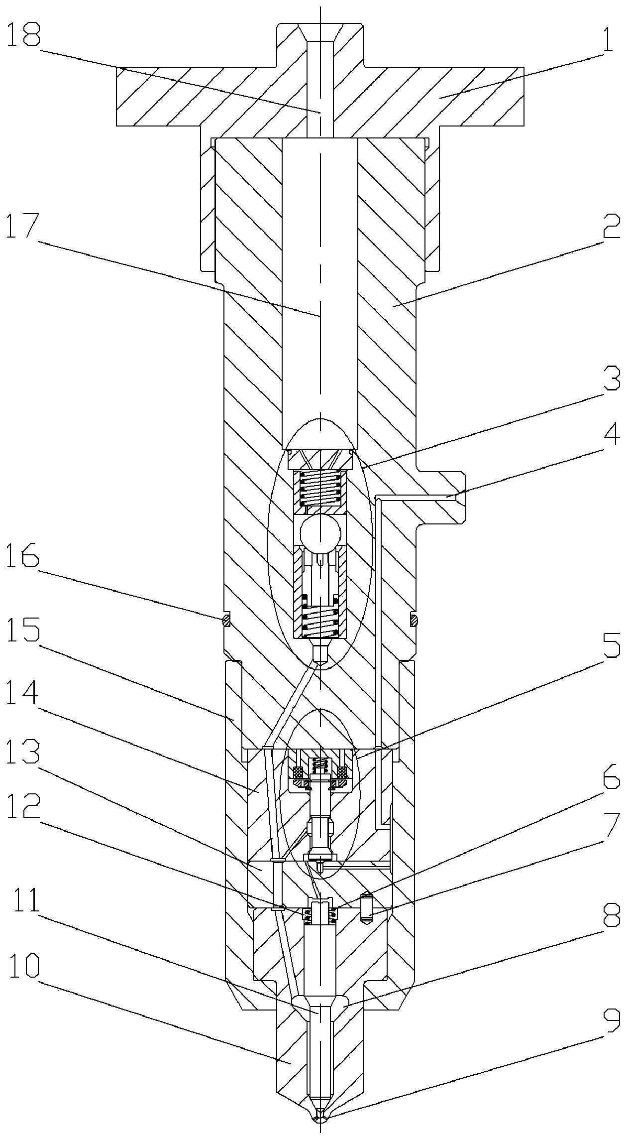
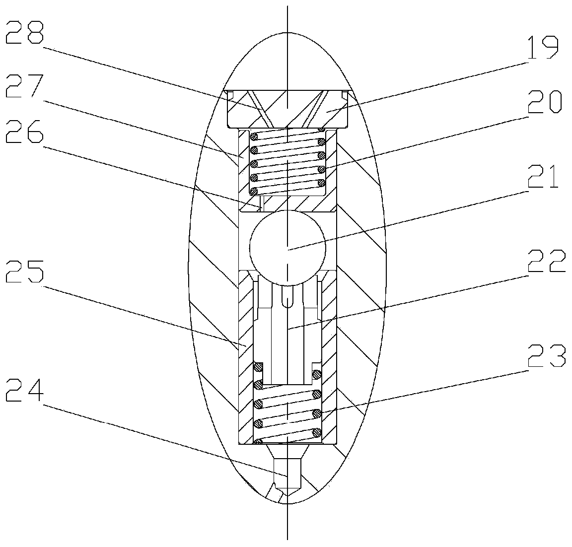
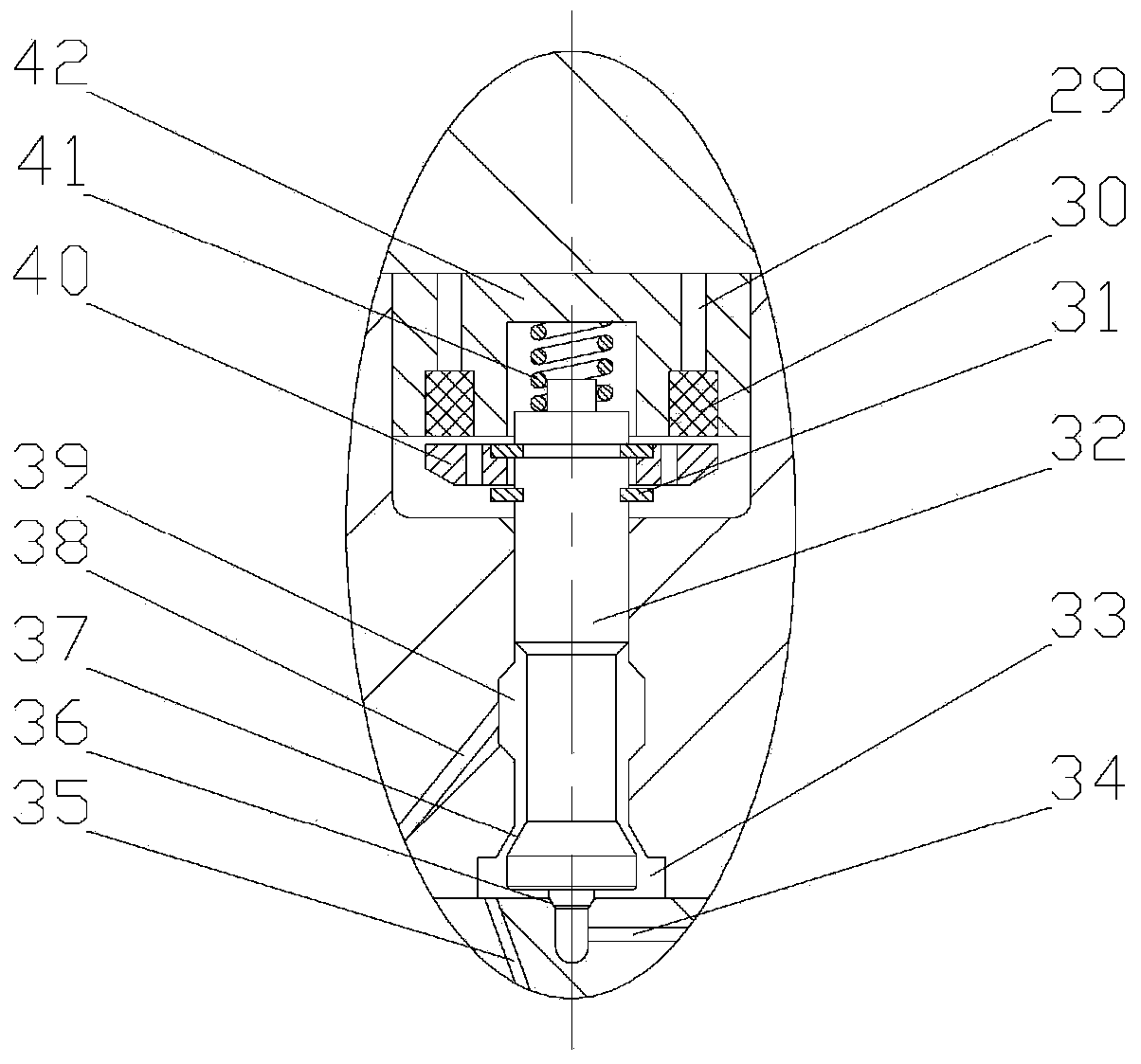
[0015] combine Figure 1~3 , the present invention is a pressure accumulating flow-limiting electromagnetic control injector, which consists of an injector head 1, an injector body 2, a current limiting assembly 3, a solenoid valve assembly 5, a needle valve return spring 6, a positioning pin 7, The nozzle 10, the needle valve 11, the needle valve limit block 13, the valve seat 14, the tight cap 15 and the sealing ring 16 are composed. It is characterized in that: the fuel injector body 2 is provided with a pressure accumulator chamber 17, the pressure accumulator chamber 17 communicates with the main oil inlet hole 18 on the injector head 1, and the oil chamber in the flow limiting piston 27 passes through the limit block 19 The first oil inlet hole 28 on the top is connected with the pressure accumulator chamber 17, and the oil chamber in the flow-limiting pist...


PUM


Abstract

The invention provides a pressure accumulation flow-limiting type electromagnetic control oil sprayer which comprises an oil sprayer head, an oil sprayer body, a flow limiting component, an electromagnetic valve component, a needle valve reset spring, a locating pin, a nozzle, a needle valve, a needle valve limiting block, a valve seat, a tightening cap and a sealing ring. A pressure accumulation cavity is formed in the oil sprayer body, the pressure accumulation cavity is respectively communicated with a main oil inlet in the oil sprayer head and a first oil passing hole in the limiting block, the flow limiting component is arranged in the oil sprayer body, the lower end of the flow limiting component is communicated with a fuel oil channel in the oil sprayer body, the needle valve cavity is communicated with a second oil cavity through a fourth oil inlet in the needle valve limiting block, a first oil cavity is communicated with a high-pressure fuel oil path in the oil sprayer body through a third oil inlet in the vale seat, an oil drainage opening is communicated with an oil return opening through a low-pressure oil path in the oil sprayer body, and the needle valve limiting block is used as a spring seat of the needle valve reset spring to be arranged at the upper end of the needle valve. The pressure accumulation flow-limiting type electromagnetic control oil sprayer is high in response speed, high in control precision, flexible in oil spraying rule and stable in work in the small oil spraying quantity spraying process.

Description

technical field [0001] The invention relates to a fuel injector, specifically a diesel fuel injector. Background technique [0002] Traditional mechanically controlled fuel injectors have the main advantages of simple structure and high operational reliability, but because the fuel injection timing, fuel injection pressure and fuel injection rate are restricted by the shape of the high-pressure fuel pump cam, it has slow fuel injection response and poor control of fuel injection. It is difficult to improve the fuel economy and emission characteristics of the engine on the basis of poor measurement accuracy and other deficiencies. Compared with the mechanically controlled injector, the electromagnetically controlled injector used in the diesel engine electronic injection system has faster response speed, flexible and controllable fuel injection characteristics, and more accurate control of the fuel injection quantity. However, it also has the following Disadvantages: The con...

Claims


Application Information

Patent Timeline
IPC IPC(8): F02M51/06F02M61/10F02M61/16
Inventor 白云范立云马修真许德王作群费红姿姚崇
Owner HARBIN ENG UNIV
Learn More