
Large-span telescopic universal tower head fixture

A telescopic, large-span technology, applied in the direction of overhead lines/cable equipment, etc., can solve the hidden dangers of operation safety and operation safety, the unavailability of seat plates and lead screws, and the unavailability of insulating pull plates, etc., to improve the operability. Sexual range, light weight, uniform force effect

Inactive Publication Date: 2014-08-27
STATE GRID CORP OF CHINA +1
View PDF4 Cites 6 Cited by
  • Summary
  • Abstract
  • Description
  • Claims
  • Application Information

AI Technical Summary

Problems solved by technology

If the force on both sides of the pulley group is uneven, it will cause greater deformation on the side where the force is greater, and there is a huge safety hazard for the safety of the operation and operation, and there are also the following problems: due to the different tower types of the line design It is also different, and there are many types of towers, some of which are available for seat plates and screw screws, and some are not available; due to different circuit designs and different types of insulators, the length and creepage are also different, and some insulating pull plates are available and some are not. Use; use the pulley block to hang directly on both sides of the cross-arm, and it is very easy to damage and deform the cross-arm under the condition of force

Method used


Image

  • Large-span telescopic universal tower head fixture
  • Large-span telescopic universal tower head fixture
  • Large-span telescopic universal tower head fixture

Examples


Embodiment Construction

[0015] Below in conjunction with accompanying drawing, the present invention is described in further detail:

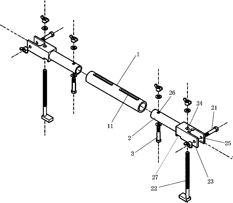
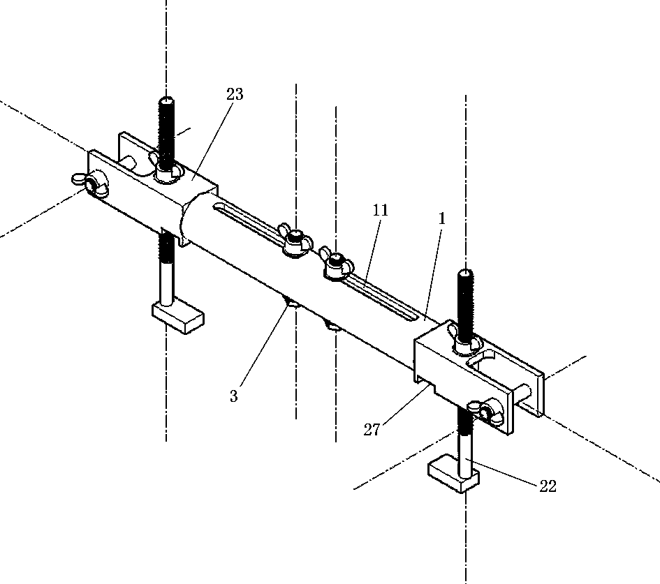
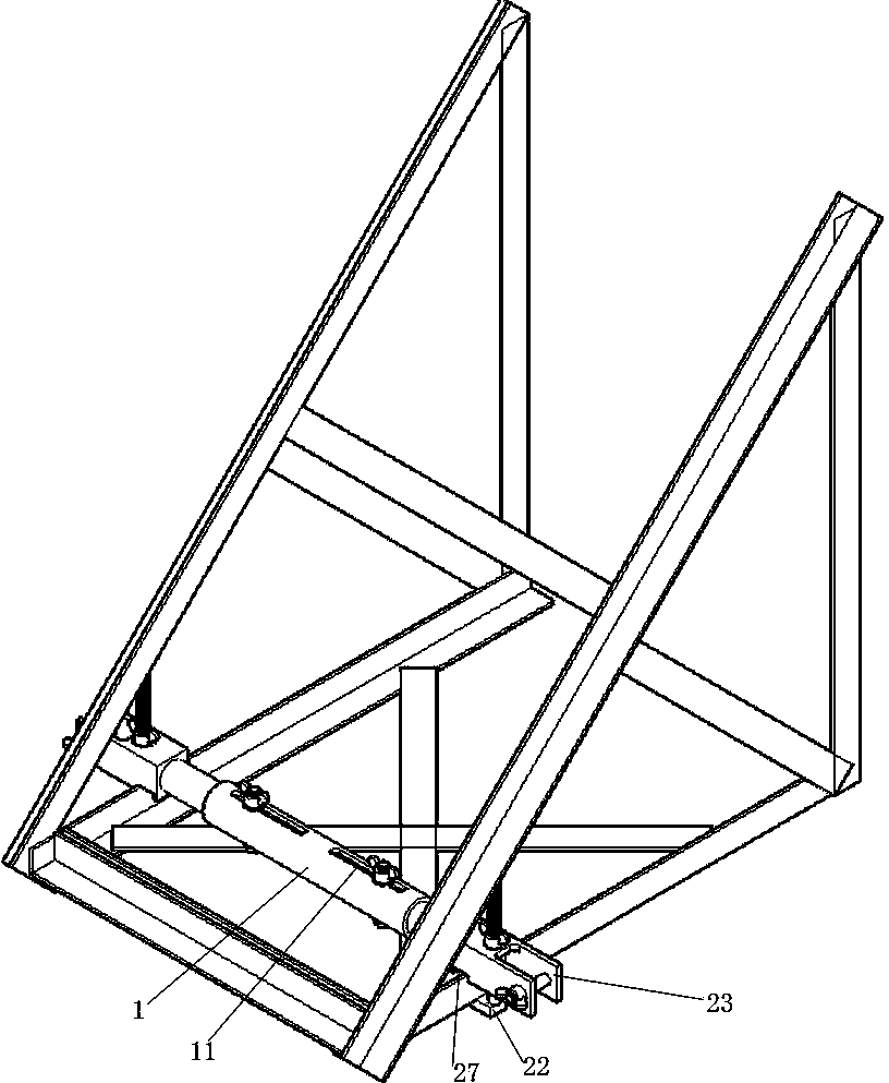
[0016] Such as figure 1 , 2 As shown, the large-span telescopic universal tower head fixture of the present invention includes an intermediate beam 1, a cover beam 2, a hook bolt 22 and a pulley line hanging rod 21, and there are two cover beams 2, which are symmetrically and flexibly connected to the middle beam. On both sides, the tail end of the sleeve beam 2 is connected with a U-shaped connector 23, and the U-shaped connector 23 is provided with a horizontal screw hole 25 and two vertical screw holes 24, and the hook bolt 22 is connected with the vertical screw hole. The U-shaped connectors are connected, and the pulley line hanging rod 21 is connected with the U-shaped connectors through horizontal screw holes.

[0017] The middle beam 1 is symmetrically provided with four long oval screw holes 11 , and the front end of the cover beam is provided with scre...


PUM


Abstract

The invention relates to a large-span telescopic universal tower head fixture. The large-span telescopic universal tower head fixture comprises an intermediate beam, two sleeve beams, hook bolts and tackle rope hanging rods. The two sleeve beams are symmetrically and movably connected to the two sides of the intermediate beam. U-shaped connectors are connected to the tail ends of the sleeve beams, and each U-shaped connector is provided with a horizontal screw hole and vertical screw holes. The hook bolts are connected with the U-shaped connectors through the vertical screw holes. The tackle rope hanging rods are connected with the U-shaped connectors through the horizontal screw holes. The large-span telescopic universal tower head fixture comprises the intermediate beam and the two sleeve beams, and the two sleeve beams are symmetrically arranged on the intermediate beam in a sleeved mode and connected with the intermediate beam through locking bolts so that the length of the portions, sleeved with the sleeve beams, of the intermediate beam and mutual dependence of stress of the two sides can be adjusted, the large-span telescopic universal tower head fixture is suitable for the widths of all cross arm heads. Due to the structure that the sleeve beams are connected with the U-shaped connectors, the intensity of pressure is increased, force bearing points of main cross arm materials can evenly bear force, and deformation caused by overlarge stress will not occur.

Description

technical field [0001] The invention relates to a jig, in particular to a large-span telescopic universal tower head jig. Background technique [0002] The traditional 220kV transmission line live replacement work of composite insulators is to use two tower head seat plates, penetrate two lead screws, lead screws connect two insulating pull plates, pull plates connect two hooks, make the hooks hook the wires, Two workers turn the lead screw to hook the wire, transfer the weight of the wire to the tool, and then replace the linear insulator. Or use block blocks to be directly hung on both sides of the cross-arm for replacement, and two sets of 3-3 block blocks are used to transfer the vertical load, and the 3-3 block blocks are directly hung on the main material of the cross-arm, which is easy to cause the main material to be damaged. Force points deform or slide. If the force on both sides of the pulley group is uneven, it will cause greater deformation on the side where t...

Claims


Application Information

Patent Timeline
Patent Type & Authority Applications(China)
IPC IPC(8): H02G1/02
Inventor 张森张浩朱义东赵东洋王东华苗中杰董政王雷
Owner STATE GRID CORP OF CHINA
Learn More