
Compressed air energy storage system

A technology of compressed air energy storage and compressed air, applied in steam engine installations, machines/engines, mechanical equipment, etc., can solve the problems of difficult and stable operation of compressors and expanders, energy loss, etc., so as to reduce power consumption and increase power output. , the effect of high efficiency

Active Publication Date: 2014-08-27
中储国能(北京)技术有限公司
View PDF9 Cites 24 Cited by
  • Summary
  • Abstract
  • Description
  • Claims
  • Application Information

AI Technical Summary

Problems solved by technology

[0003] At present, large-scale power energy storage system technologies include pumped water storage and compressed air energy storage. Pumped water storage technology is limited by terrain, while the pressure in the gas storage device of traditional compressed air energy storage technology changes. During the compression process, gas storage The pressure of the device keeps increasing, while the pressure keeps dropping during the expansion process, which makes it difficult for the compressor and expander to work stably and causes a large amount of energy loss

Method used


Image

  • Compressed air energy storage system
  • Compressed air energy storage system
  • Compressed air energy storage system

Examples


Embodiment Construction

[0029] In order to make the object, technical solution and advantages of the present invention clearer, the present invention will be described in further detail below in conjunction with specific embodiments and with reference to the accompanying drawings. It should be noted that, in the drawings or descriptions of the specification, similar or identical parts all use the same figure numbers. Implementations not shown or described in the accompanying drawings are forms known to those of ordinary skill in the art. Additionally, while illustrations of parameters including particular values ​​may be provided herein, it should be understood that the parameters need not be exactly equal to the corresponding values, but rather may approximate the corresponding values ​​within acceptable error margins or design constraints.

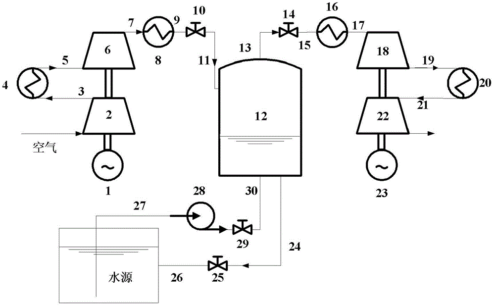
[0030] The compressed air energy storage system of the present invention presses the air into the gas storage device through the compressor when the power is l...


PUM


Abstract

The invention provides a compressed air energy storage system. The compressed air energy storage system comprises an energy storage assembly, an air storage device, a water pump and an energy releasing assembly; the air storage device is a closed container for prestoring water; the water pump is arranged on a pipeline of the gas storage device; the energy storage assembly comprises an electromotor and a compressed unit which is provided with at least one compressor; a rotary shaft of the compressed unit is connected with a rotary shaft of the electromotor; an air outlet of the compressed unit is connected with an air inlet of the air storage device through a valve; the energy releasing assembly comprises an electric generator and an expansion unit which is provided with at least one expansion machine; a rotary shaft of the expansion unit is connected with a rotary shaft of the electric generator; an air inlet of the expansion unit is connected with an air outlet of the gas storage device through a valve. According to the compressed air energy storage system, the expansion unit and the compressed unit work under constant pressure and the energy storage system is high in efficiency and good in safety.

Description

technical field [0001] The invention relates to the technical field of electric power storage, in particular to a compressed air energy storage system. Background technique [0002] In recent years, the number of large units in my country's power grid has continued to increase, the power system's own power regulation capability has been limited, and the peak-to-valley ratio of the system load has continued to increase. In order to ensure the safe and economical operation of the power grid, it is necessary to build a power energy storage system. In particular, the large-scale development of wind power, due to its intermittent characteristics, threatens the security of the power grid. In order to use renewable energy such as wind energy more efficiently, it is necessary to have a power storage system to match it. [0003] At present, large-scale power energy storage system technologies include pumped water storage and compressed air energy storage. Pumped water storage technol...

Claims


Application Information

Patent Timeline
Patent Type & Authority Applications(China)
IPC IPC(8): F01K27/00
Inventor 陈海生张雪辉严晓辉李文谭春青
Owner 中储国能(北京)技术有限公司
Learn More