
Dual channel multi-stage jet sampling pigtail

A dual-channel, jet tube technology, applied in the direction of extracting undisturbed core devices, earth cube drilling, etc., can solve the problems of prolonged sampling time, small sampling volume, and inability to take out samples, etc., and achieve the effect of increasing the airflow velocity

Active Publication Date: 2016-06-08
CHINA COAL TECH & ENG GRP CHONGQING RES INST CO LTD
View PDF6 Cites 0 Cited by
  • Summary
  • Abstract
  • Description
  • Claims
  • Application Information

AI Technical Summary

Problems solved by technology

[0004] In view of this, the purpose of the present invention is to provide a dual-channel multi-stage jet sampling pigtail to solve the problems of the existing double-wall drill sampling device after the increase in the length of the drill pipe, such as low sampling volume, prolonged sampling time and inability to take out samples. question

Method used


Image

  • Dual channel multi-stage jet sampling pigtail
  • Dual channel multi-stage jet sampling pigtail
  • Dual channel multi-stage jet sampling pigtail

Examples


Embodiment 1

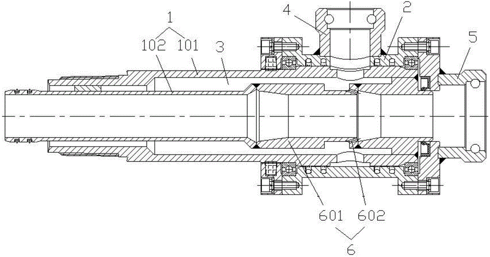
[0019] Embodiment one: if figure 1 As shown, the dual-channel multi-stage injection sampling pigtail in this embodiment includes a double-walled pipe body 1 and a housing 2 that is sheathed on the double-walled pipe body 1, and the housing 2 and the double-walled pipe body 1 are rotatably fitted;

[0020] The double-wall pipe body 1 includes an outer pipe wall 101 and an inner pipe wall 102, the annular channel 3 between the outer pipe wall 101 and the inner pipe wall 102 is closed at the rear end of the pipe body, and the outer pipe wall 101 and the inner pipe wall The front end of the pipe wall 102 is provided with a connecting structure connecting the double-walled drill pipe. The connecting structure in this embodiment includes an external thread arranged at the front end of the outer pipe wall 101 and an annular protrusion arranged at the front end of the inner pipe wall 102;

[0021] The housing 2 is provided with a first quick joint 4 communicating with the annular chan...

Embodiment 2

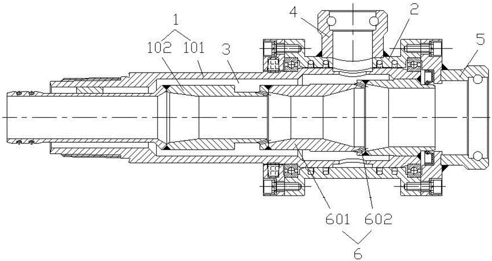
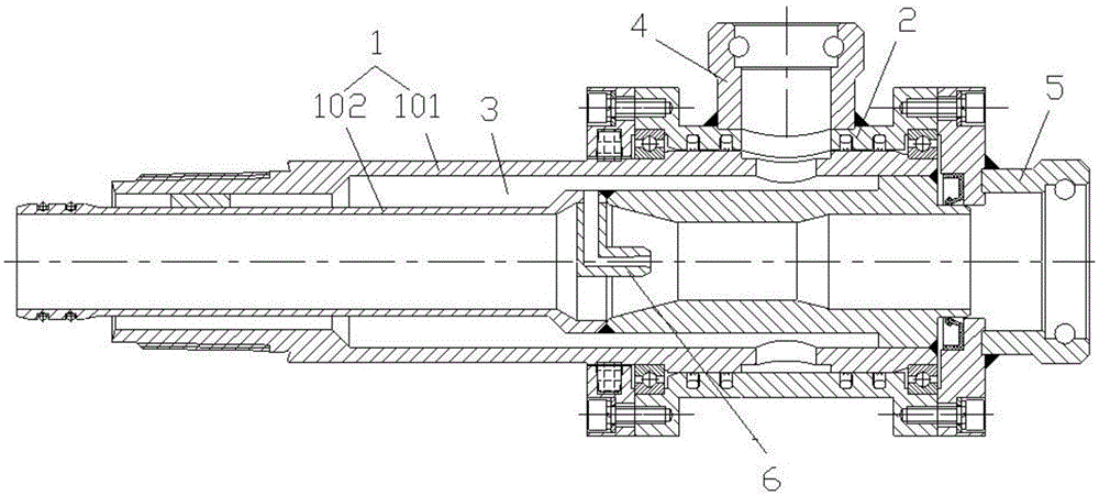
[0026] Embodiment two: if image 3 As shown, the difference between this embodiment and Embodiment 1 is that the injector 6 is a central injector, and the central injector 6 is an injection tube located in the tube hole of the inner tube wall 102, and the injection medium of the injection tube The inlet communicates with the annular channel 3 between the outer pipe wall 101 and the inner pipe wall 102; other structures of this embodiment are the same as those of the first embodiment, and will not be repeated here. The central injector in this embodiment is a single-stage central injector composed of a single injection tube. Of course, the central injector described in different implementations can also be arranged in parallel axially along the inner tube wall 102 by several injection tubes. A multi-stage central injector (such as Figure 4 As shown), the multi-stage injector can form a higher negative pressure in the tube hole of the inner tube wall 102, which is beneficial t...


PUM


Abstract

The invention discloses a two-channel multi-stage spray sampling tail braid which comprises a double-wall pipe and a shell arranged on the outer portion of the double-wall pipe in a sleeved mode. The double-wall pipe comprises an outer pipe wall and an inner pipe wall, an annular channel between the outer pipe wall and the inner pipe wall is sealed at the rear end of the pipe, and a connecting structure used for being connected with a double-wall drilling rod is arranged at the front end of the outer pipe wall and the front end of the inner wall. The shell is provided with a first fast joint communicated with the annular channel and a second fast joint communicated with a pipe hole of the inner pipe wall. The inner pipe wall is provided with a spay device for carrying out spraying towards the inner pipe wall. In the sampling process, the double-wall drilling rod is connected to the front end of the double-wall pipe, and a sample is conveyed out form the front end of the double-wall drilling rod along the pipe hole of the inner pipe wall through compressed air. Due to the fact that the spray device arranged on the inner pipe wall sprays high-speed air flow to the pipe hole of the inner pipe wall, negative pressure is formed in the pipe hole of the inner pipe wall, the speed of the air flow for conveying the sample can be enlarged, and it is ensured that the sample can be fast conveyed out with sufficient quantity under the condition that the sampling depth is enlarged.

Description

technical field [0001] The invention relates to a gas content measuring device, in particular to a dual-channel multi-stage jet sampling pigtail. Background technique [0002] The traditional tailpipe only has the function of simple water supply and air supply, which cannot meet the requirements of the specific link of sampling in the field of direct measurement of underground gas content. [0003] Compared with the single-wall structure of traditional drilling tools, the sampling devices based on the principle of reverse circulation are all double-wall structures. In reverse circulation sampling on site, as the sampling depth increases, the length of the drill pipe gradually increases. The increase in the length of the drill pipe will significantly increase the resistance along the path of the gas flowing in the drilling tool, and the power to transport the sample will decrease. Lead to the small amount of sampling, the prolongation of sampling time, and even the situation...

Claims


Application Information

Patent Timeline
Patent Type & Authority Patents(China)
IPC IPC(8): E21B25/02
Inventor 胡千庭文光才隆清明王艺树李秋林吕贵春刘胜张睿李建功张宪尚赵旭生冯康武刘志伟
Owner CHINA COAL TECH & ENG GRP CHONGQING RES INST CO LTD
Learn More