Supporting device capable of achieving rapid and continuous change of angle and bearing large load

A technology of supporting device and changing angle, which is applied in the direction of measuring device, engine test, machine/structural component test, etc. data and other issues, to achieve the effect of changing the angle quickly, accurately and continuously

Inactive Publication Date: 2014-08-13
CHINA ACAD OF AEROSPACE AERODYNAMICS
View PDF6 Cites 3 Cited by
  • Summary
  • Abstract
  • Description
  • Claims
  • Application Information

AI Technical Summary

Problems solved by technology

Due to the limitation of the working characteristics of the engine and the test conditions, the test time of the aerospace engine on the ground is generally very short, and the engine is mostly tested in a horizontal position, and a small number of tests with angles are also realized by the pre-bias device. One test run The test can only measure data at one angle
With the development of engine development technology, the load of the engine test is getting larger and larger, and the demand for test data is also increasing. The test with yaw angle state brings a large side load, so The current test support device can no longer meet the development requirements of the engine, and it is necessary to develop a fast and continuously variable angle support device that can withstand large loads as the test equipment for the engine test run
There is no public report of similar continuously variable angle devices in China, and there are few reports of such test devices in foreign countries, and no relevant information has been found.

Method used


Image

  • Supporting device capable of achieving rapid and continuous change of angle and bearing large load
  • Supporting device capable of achieving rapid and continuous change of angle and bearing large load
  • Supporting device capable of achieving rapid and continuous change of angle and bearing large load

Examples


Embodiment Construction

[0024] The present invention will be described in further detail below in conjunction with the accompanying drawings.

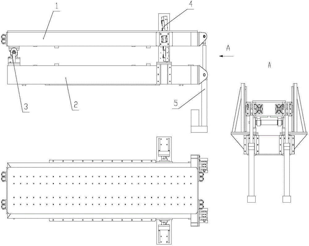
[0025] Such as figure 1 As shown, the present invention is made up of upper platform 1, lower platform 2, rotating shaft device 3, arc guide rail device 4 and driving device 5. Since the variable-angle support device needs to drive the test piece to rotate, the design of the device consists of upper and lower platforms. The lower platform 2 is a fixed part, which is connected to the installation foundation and is the support of the whole device. The upper platform 1 is installed on the lower platform through the rotating shaft device 3. 2, and can rotate relative to the lower platform 2; the upper platform 1 is a moving part: connected to the engine test piece, and rotates relative to the lower platform 2 around the rotating shaft; The center of rotation supports the upper platform 1 at the same time; the arc guide rail device 4: connects the upper and lower...


PUM


Abstract

The invention relates to a supporting device capable of achieving rapid and continuous change of an angle and bearing a large load. The supporting device capable of achieving rapid and continuous change of the angle and bearing the large load is composed of an upper platform and a lower platform, wherein the upper platform is movable and moves along with an engine test article during a test, the lower platform is fixed and is connected with an installation base, the upper platform and the lower platform are connected through a rotary shaft device, arc-shaped guide rail devices and a driving device, the rotary shaft device is installed between one side of the upper platform and one side of the lower platform, the driving device is installed between the other side of the upper platform and the other side of the lower platform, and the upper platform rotates relative to the lower platform around the rotary shaft; an angle sensor is installed at one end of the rotary shaft so that angle detection can be achieved easily; the arc-shaped guide rail devices are installed on the two sides of the upper platform and the lower platform and can limit the moving trajectory of the upper platform and bear the load in the horizontal direction. The driving device is formed by combining two electric cylinders and a high-power servo motor, large pushing force can be provided, and rapid and accurate positioning of an angle can be achieved.

Description

technical field [0001] The invention is used in the ground test drive test of aerospace engines under high-altitude environment and high Mach number conditions. Background technique [0002] The invention relates to a variable-angle supporting device for a ground test drive test of an aerospace engine. Due to the limitation of the working characteristics of the engine and the test conditions, the test time of the aerospace engine on the ground is generally very short, and the engine is mostly tested in a horizontal position, and a small number of tests with angles are also realized by the pre-bias device. One test run The test can only measure the data under one angle state. With the development of engine development technology, the load of the engine test is getting larger and larger, and the demand for test data is also increasing. The test with yaw angle state brings a large side load, so The current test support device can no longer meet the development requirements of...

Claims


Application Information

Patent Timeline
Patent Type & Authority Applications(China)
IPC IPC(8): G01M15/02
Inventor 孙侃赵金海曾令民
Owner CHINA ACAD OF AEROSPACE AERODYNAMICS
Why Eureka
Try Eureka