
Demoulding device

A technology of demolding device and sliding block is applied in the field of demolding device, which can solve the problems of incapable demolding and ejection of products, complex structure, etc., and achieve the effects of guaranteed mold life, low mold cost and strong structural reliability.

Active Publication Date: 2014-08-13
NINGBO HUABAO PLASTICS & RUBBER MOLD
View PDF6 Cites 3 Cited by
  • Summary
  • Abstract
  • Description
  • Claims
  • Application Information

AI Technical Summary

Problems solved by technology

This structure is quite complicated
And in some cases, there may not be enough space to complete it, and the product cannot be demolded and ejected normally.

Method used


Image

  • Demoulding device
  • Demoulding device
  • Demoulding device

Examples


Embodiment Construction

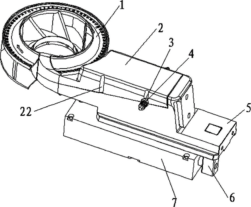
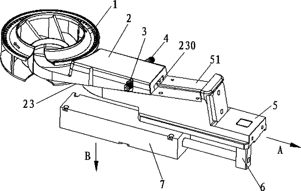
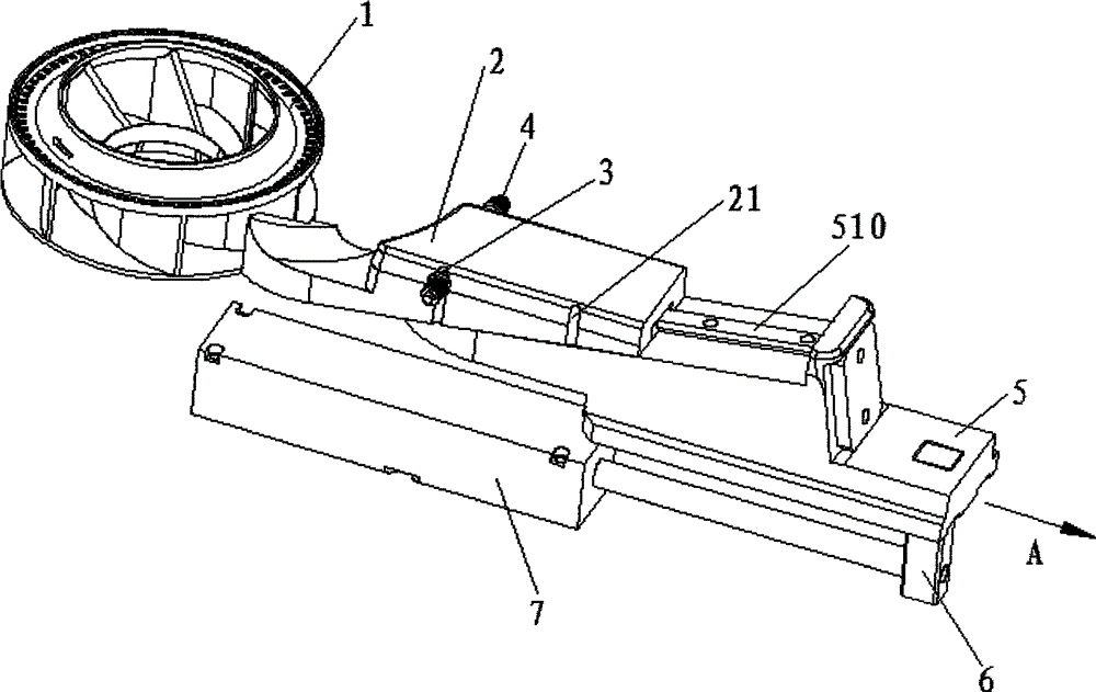
[0015] see Figure 1 to Figure 5 As shown, the demoulding device of the present invention is used for molding products 1 and includes a lower slider 5, an upper slider 2 assembled above the lower slider 5, a connecting rod 6 and a limit pin 52 assembled on the lower slider 5, assembled on The oil cylinder 7 on the connecting rod 6, the bead (not shown) positioned at both sides of the lower slider 5 and the dial ball 3 and the spring 4 assembled on the bead. The upper slider 2 and the lower slider 5 are connected together with the product 1 for forming the product 1 .

[0016] The upper slider 2 is assembled above the lower slider 5 and can slide relative to the lower slider 5 . The lower slider 5 is provided with an inclined top surface 51 . The top surface 51 is provided with a T-shaped guide rail 510 . The upper slider 2 is provided with an inclined bottom surface 23 assembled on said inclined top surface 51 . The bottom surface 23 is provided with a T-shaped sliding slo...


PUM


Abstract

The invention relates to a demoulding device which contains a lower sliding block, an upper sliding block, a connecting rod, a spacer pin, a dialing bead, a spring and an oil cylinder. The lower sliding block and the upper sliding block are connected with a product. The lower sliding block is provided with an inclined top surface. The upper sliding block is provided with an inclined undersurface which is assembled on the top surface. The upper sliding block is equipped with a chute for holding the spacer pin and a front groove for holding the dialing bead. The height of the front groove in the vertical direction is greater than the height of the dialing bead. During mould-opening, the oil cylinder drives the connecting rod to move so as to drive the lower sliding block to move to separate from a product. during movement of the lower sliding block, the spring presses the dialing bead into the front groove such that the upper sliding block only can move downward along the vertical direction. Simultaneously, the spacer pin moves along the chute until the spacer pin presses against the upper sliding block. At the moment, the dialing bead separates from the front groove, and the motion force of the lower sliding block makes the spacer pin drive the upper sliding block to move away from the product so as to separate the upper sliding block from the product.

Description

【Technical field】 [0001] The invention relates to a demoulding device in mold processing. 【Background technique】 [0002] During the processing of injection molds, many products are provided with undercuts in the fixed mold direction. At present, the molds used in the factory are generally equipped with push rods and oil cylinders on the side of the movable mold, which are used to automatically disengage the mold. Therefore, when designing the mold, the core pulling action is completed by the push plate and then the demoulding is performed. This structure is quite complicated. Moreover, in some cases, there may not be enough space to complete, and the normal demoulding and ejection of products cannot be performed. [0003] In view of this, it is necessary to provide an improved demoulding device to overcome the defects of the prior art. 【Content of invention】 [0004] The object of the present invention is to provide a demoulding device with simple structure and conven...

Claims


Application Information

Patent Timeline
Patent Type & Authority Applications(China)
IPC IPC(8): B29C45/40
CPCB29C45/332B29C2045/334
Inventor 华明伟尤建国
Owner NINGBO HUABAO PLASTICS & RUBBER MOLD
Learn More