Moving equipment with bone conduction function
A mobile device, bone conduction technology, applied to the structure of telephones, etc., can solve problems such as increased costs, unusable, hearing impairment, etc., and achieve the effect of reducing costs
- Summary
- Abstract
- Description
- Claims
- Application Information
AI Technical Summary
Problems solved by technology
Method used
Image

Examples
Embodiment 1
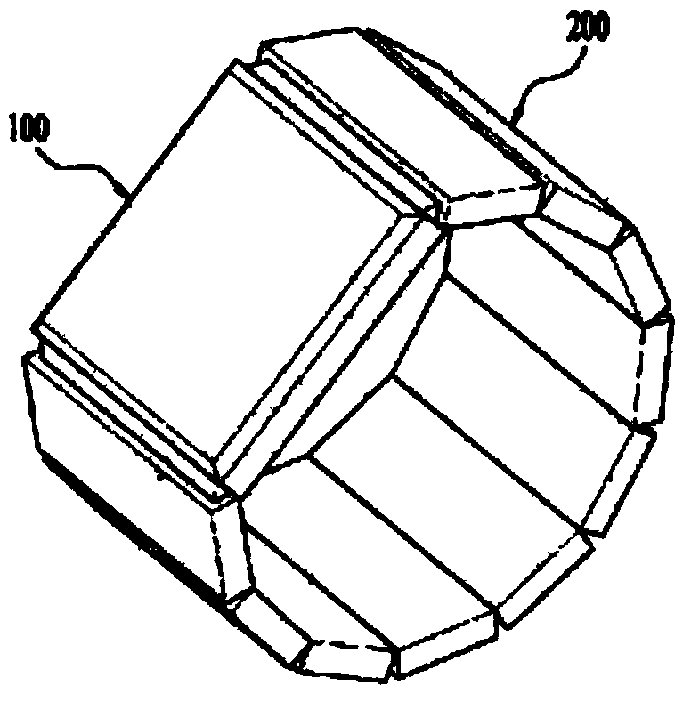
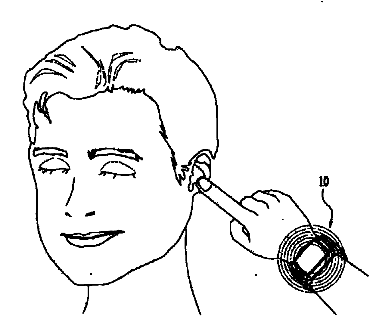
[0050] figure 1 It is an appearance view of a wrist watch type mobile device with bone conduction function according to the present invention. according to figure 1 As shown, the mobile device carrier device with bone conduction function, the carrier device includes a case 100, and a belt 200 for fastening the case 100 to a part of the user's body.
[0051]The carrier device of the present invention is equipped with an audio signal generating module, and the audio signal generating module can emit audio received from the wireless communication module or stored in memory in signal receiving, call mode or recording mode, voice recognition mode, and broadcast receiving mode. For example, when the user talks or plays music, the carrier device will send out an audio signal. This audio signal generation module includes a receiver, a speaker, a buzzer, etc., and the vibrator 130 will The audio signal produces vibrations.
[0052] Meanwhile, the front of the housing 100 of the carr...
Embodiment 2
[0069] Figure 6 is a block diagram of another mobile device with bone conduction function.
[0070] Such as Figure 6 As shown, the present invention includes a case 100 constituting the appearance of a mobile device with bone conduction function, a groove 300 formed on the outer surface of the case 100 , and a belt 200 for fastening the case 100 to the user's body.
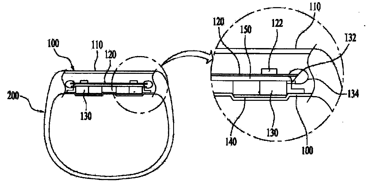
[0071] Wherein, the casing 100 includes a circuit board 120 and a display panel 110 electrically connected to the circuit board 120 . The vibrator 130 is embedded in the groove 300 to form an electrical connection with the circuit board 120 .
[0072] Meanwhile, the first connector 132 capable of forming an electrical connection with the second connector 122 is disposed on the upper surface of the vibrator 130 embedded in the groove 300 . The buffer member 140 is arranged on the lower surface of the vibrator 130 fitted into the groove 300 . At the same time, a cover 160 capable of covering the vibrator 130 a...
Embodiment 3
[0078] Figure 7 It is a structural schematic diagram of another mobile device with bone conduction function according to the present invention.
[0079] Such as Figure 7 As shown, the present invention includes a case 100 constituting the appearance of a mobile device with bone conduction function, and a belt 200 for fastening the case 100 on the user's body. The interior of the case 100 contains a circuit board 120 and forms a The display panel 110 electrically connected to the belt 200 is equipped with a vibrator 130 electrically connected to the circuit board 120 .
[0080] Wherein, the upper part of the vibrator 130 is equipped with a buffer component 140 , and the lower part is equipped with an insulating component 150 .
[0081] Meanwhile, the buffer member 140 is made to face the inner direction of the user's body, and placed between the outer case 210 of the belt 200 and the vibrator 130 . The insulating member 150 is made to face the outward direction, and placed...
PUM
 Abstract
Description
Claims
Application Information
 - Generate Ideas
- Intellectual Property
- Life Sciences
- Materials
- Tech Scout
- Unparalleled Data Quality
- Higher Quality Content
- 60% Fewer Hallucinations
Browse by: Latest US Patents, China's latest patents, Technical Efficacy Thesaurus, Application Domain, Technology Topic, Popular Technical Reports.
© 2025 PatSnap. All rights reserved.Legal|Privacy policy|Modern Slavery Act Transparency Statement|Sitemap|About US| Contact US: help@patsnap.com