Combined exhaust passage independently installed in layered mode

A layered, independent and combined technology, applied in the direction of vertical pipes, building components, buildings, etc., can solve the problems of exhaust ducts hanging and falling, having no practical value, and occupying space, so as to facilitate maintenance or replacement, save raw materials, The effect of improving productivity

Inactive Publication Date: 2014-08-06
张家口市宝通建筑配套制品厂
View PDF11 Cites 5 Cited by
  • Summary
  • Abstract
  • Description
  • Claims
  • Application Information

AI Technical Summary

Problems solved by technology

The disadvantage is that the superimposed installation of unit components on each floor becomes the support of the exhaust duct components on the upper floor. If the integrated exhaust duct is damaged or there is a problem with the variable pressure exhaust duct, the replacement of the unit components will cause the upper floor to be exhausted. The exhaust duct of the air-conditioned air-conditioning system is hanging and falling, which brings a lot of difficulties and inconvenience to the maintenance and construction, while the exhaust duct of the rectangular column is close to the column wall of the wall by the corner, which wastes materials and takes up space, has no practical value, and is only superimposed Play the role of some stable support when installing the unit components of each floor

Method used


Image

  • Combined exhaust passage independently installed in layered mode
  • Combined exhaust passage independently installed in layered mode
  • Combined exhaust passage independently installed in layered mode

Examples


Embodiment Construction

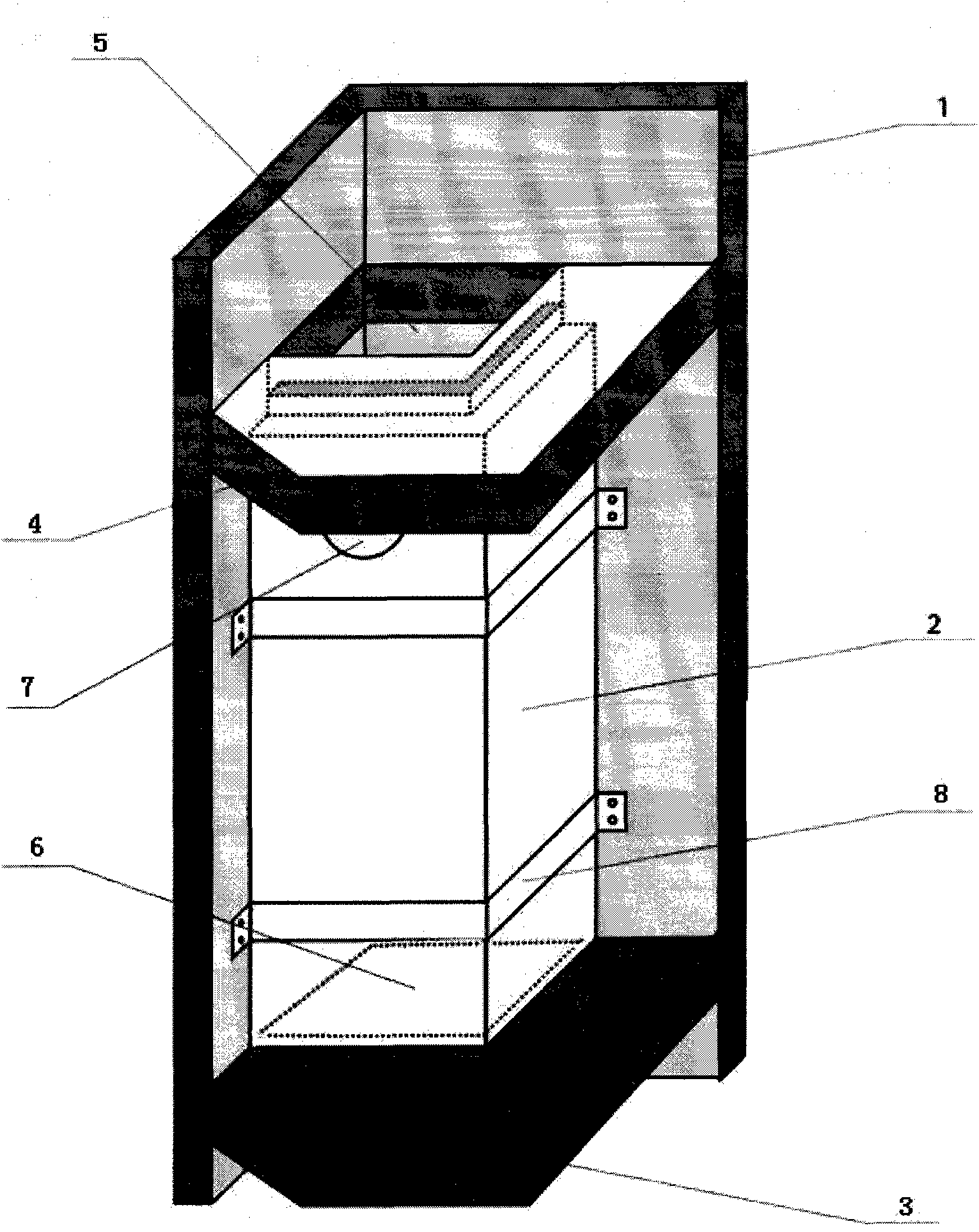
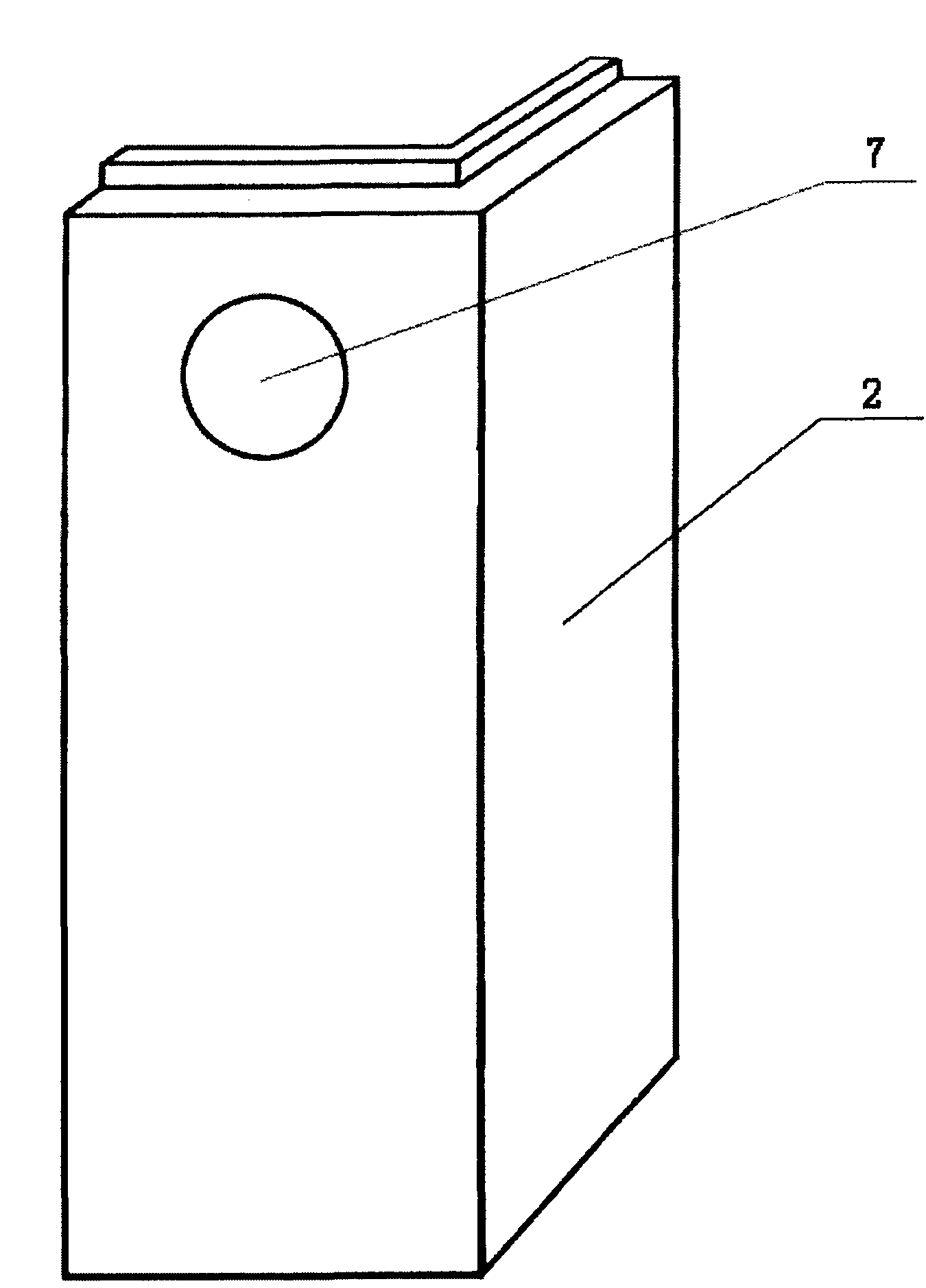
[0012] Embodiments of the present invention will be further described below in conjunction with the accompanying drawings.

[0013] Refer to attached figure 1 , figure 2 , image 3 It can be seen that a combined exhaust duct installed independently in layers consists of a vertical wall 1, a right-angle strip plate 2, a lower floor 3, an upper floor 4, an upper reserved installation opening 5, a lower reserved installation opening 6, and a row Composed of air holes 7 and fixed metal hoops 8; it is characterized in that: the combined exhaust duct is formed by the vertical wall 1 on both sides of the vertical corner of the room and the right-angle strip plate 2, and the upper end of the right-angle strip plate 2 is The step interpolation structure, the step interpolation part is inserted into the reserved installation opening 5 on the upper floor 4, the width of the two vertical sides of the right-angle strip plate 2 is respectively larger than the corresponding aperture side ...


PUM


Abstract

The invention discloses a combined exhaust passage independently installed in a layered mode. The combined exhaust passage independently installed in the layered mode is formed by indoor vertical walls and a right-angled strip-type board in an enclosing mode, wherein the vertical walls are arranged on the two sides of a vertical wall corner. The upper end of the right-angled strip-type board is of a stepped internal insertion structure, wherein the widths of the two perpendicular side faces of the right-angled strip-type board are larger than the corresponding opening side lengths of a lower preformed mounting opening in a lower floor respectively; the stepped internal insertion structure is inserted into an upper preformed mounting opening in an upper floor; the bottom end of the right-angled strip-type board is located on the lower floor on the edges of the lower preformed mounting opening. The combined exhaust passage can be installed independently in the layered mode and supported by the floors, and as a result, the defects of inconvenient maintenance and replacement caused by a supporting system of an existing exhaust passage that the existing exhaust passage is installed from bottom to top in an overlapped mode are overcome; meanwhile, through combination of section bars and the wall, raw materials are saved, the production efficiency is improved, and the combined exhaust passage is easy and convenient to operate in the installation process; a variable pressure plate assembly is particularly suitable for being arranged on the combined exhaust passage, then the exhaust passage with a variable pressure function is manufactured, and the combined exhaust passage is convenient to maintain after being used and has obvious practical value.

Description

technical field [0001] The invention relates to the technical field of building supporting products, in particular to an exhaust duct for removing peculiar smell and cooking fumes in kitchens and bathrooms. Background technique [0002] At present, kitchens and toilets in residential buildings are used to remove odors and oily fumes. No matter the traditional exhaust duct or the improved variable pressure exhaust duct, most of them are prefabricated with steel bars and concrete. The unit components are hollow rectangular columns. And install it in the floor of the completed residential building of the main body in the reserved exhaust opening at the corner of the wall. From the lowest floor, the unit components are stacked one by one to form an exhaust duct that runs through from top to bottom. The disadvantage is that the superimposed unit components on each floor become the support of the exhaust duct components on the upper floor. If the integrated exhaust duct is damaged...

Claims


Application Information

Patent Timeline
Patent Type & Authority Applications(China)
IPC IPC(8): E04F17/02
Inventor 李万成
Owner 张家口市宝通建筑配套制品厂
Why Eureka
Try Eureka