Diesel injector for diesel engine
A fuel injector and diesel engine technology, applied in the direction of machines/engines, mechanical equipment, engine components, etc., can solve problems such as deformation, affecting the performance of electronically controlled fuel injectors, and increasing the radial friction between the needle valve body and the needle valve. Achieve the effects of reducing deformation, improving precision and motion stability, and reducing radial friction
- Summary
- Abstract
- Description
- Claims
- Application Information
AI Technical Summary
Problems solved by technology
Method used
Image

Examples
Embodiment 1
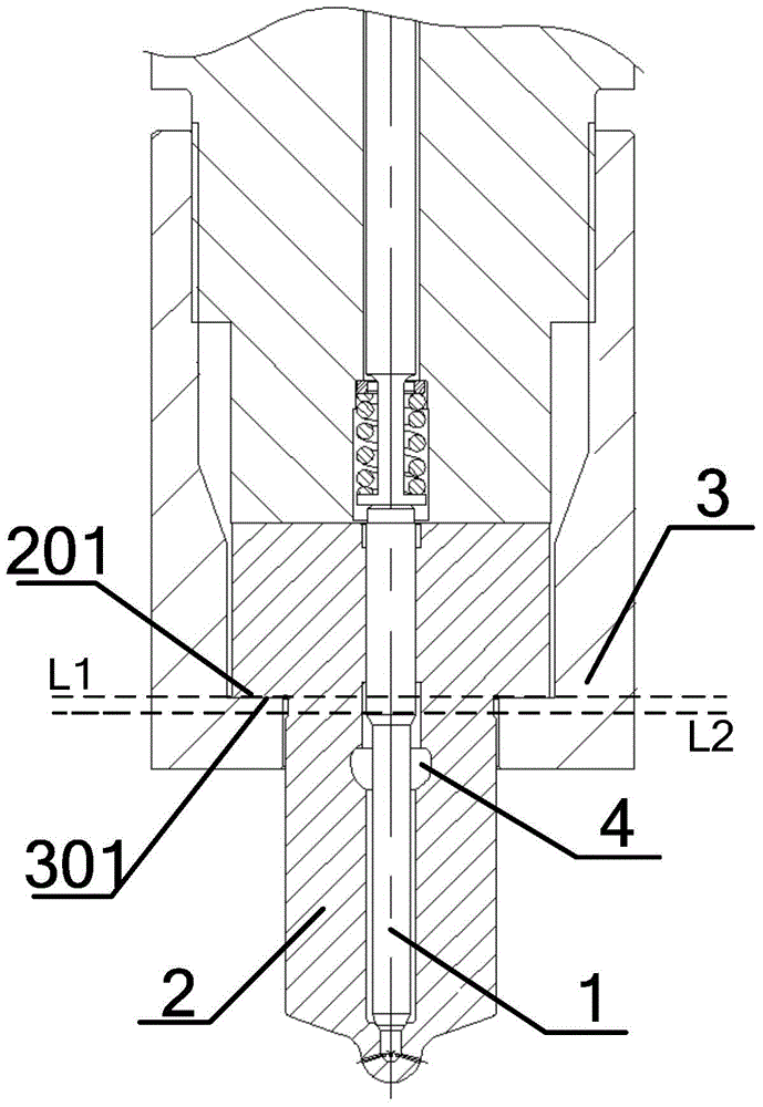
[0032] Such as figure 1 As shown, a fuel injector for a diesel engine includes a needle valve 1, a needle valve body 2, a fastening nut 3, and an oil chamber 4, etc. The needle valve 1 and the needle valve body 2 constitute a needle valve assembly. The needle valve 1 is arranged in the needle valve body 2 through precision fitting. The needle valve body 2 has a supporting surface 201, and the fastening nut 3 has a protrusion 301. The needle valve The annular lower surface of the supporting surface 201 of the body 2 is attached to the annular upper surface of the protruding part of the fastening nut 3 to form a mating sealing surface. The oil chamber 4 is arranged between the needle valve 1 and the needle valve body 2. The plane of the sealing surface formed by the supporting surface 201 of the needle valve body 2 and the protrusion 301 of the fastening nut 3 is set as L1, and the plane of the top surface of the oil chamber 4 is set as L2. In the case that the plane L2 where th...
Embodiment 2
[0046] The fuel injector for diesel engine provided in this embodiment is similar in structure to the fuel injector in embodiment 1, and also includes a needle valve 1, a needle valve body 2, a fastening nut 3, and an oil receiving cavity 4 Wait. The connection relationship between the components is the same as that described in Embodiment 1, and will not be repeated here.
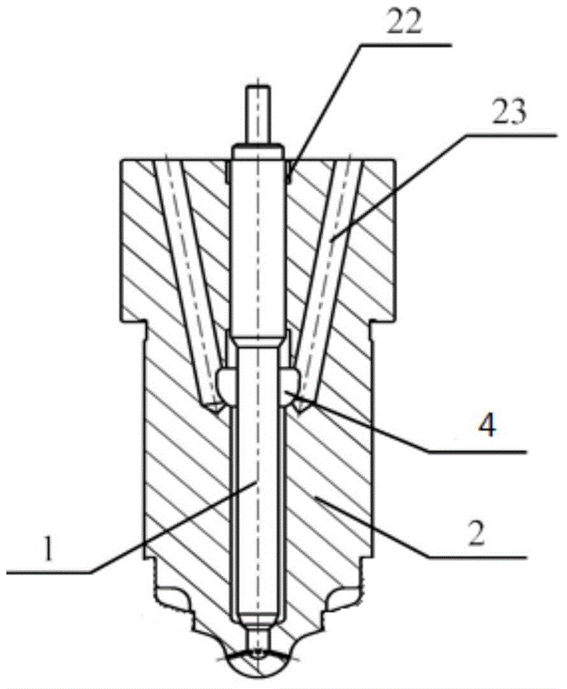
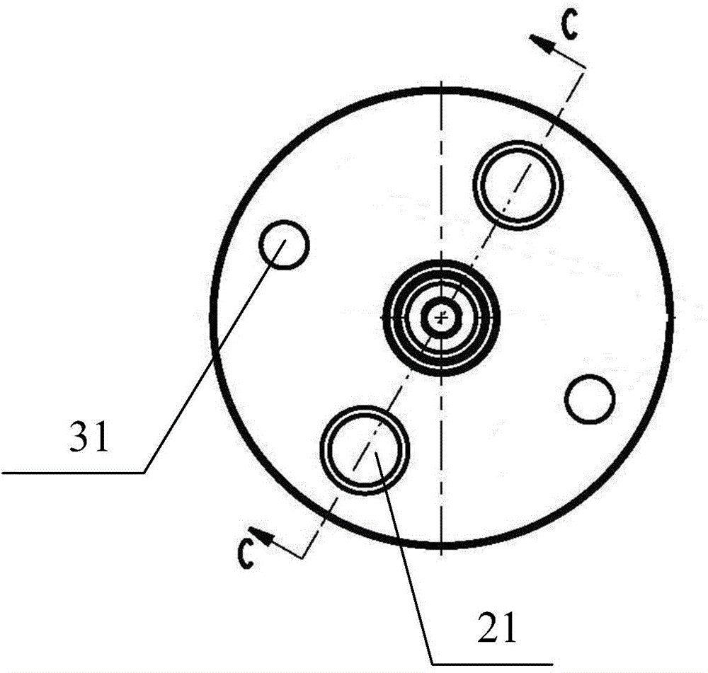
[0047] The difference from Example 1 is that the combination figure 2 — Figure 4 In the fuel injector provided in this embodiment, the needle valve body 2 is provided with two symmetrical positioning pin holes 21 and two symmetrical oil inlet passages 23. The positioning pin hole 21 is provided on the upper surface of the needle valve body 2 vertically downward in the axial direction. See figure 2 with image 3 One end of the oil inlet passage 23 located in the needle valve body 2 is connected with the oil receiving cavity 4, and the other end is formed with two oil inlet holes 31 on the upper surface of...
Embodiment 3
[0059] In this embodiment, the fuel injector provided in this embodiment has a similar structure to the fuel injector in embodiment 1 or 2, and also includes a needle valve 1, a needle valve body 2, a fastening nut 3, and Oil chamber 4 etc. The connection relationship between the components is the same as that described in Embodiment 1 or 2, and will not be repeated here.
[0060] Different from Example 1 or 2, the combination figure 2 , The inner side of the needle valve body 2 is provided with a reaming hole 22, which is located at the uppermost end of the mating surface of the needle valve body 2 and the needle valve 1. The width (diameter) of the reaming hole 22 in the radial direction and the depth in the axial direction are not less than the radial deformation of the needle valve body 2 and the needle valve 1. Specifically, the diameter of the enlarged hole 22 is increased by 0.1 to 3 mm from the diameter of the needle valve 1. The depth of the reamer 22 in the axial dir...
PUM
| Property | Measurement | Unit |
|---|---|---|
| Radial clearance | aaaaa | aaaaa |
Abstract
Description
Claims
Application Information
 - R&D
- Intellectual Property
- Life Sciences
- Materials
- Tech Scout
- Unparalleled Data Quality
- Higher Quality Content
- 60% Fewer Hallucinations
Browse by: Latest US Patents, China's latest patents, Technical Efficacy Thesaurus, Application Domain, Technology Topic, Popular Technical Reports.
© 2025 PatSnap. All rights reserved.Legal|Privacy policy|Modern Slavery Act Transparency Statement|Sitemap|About US| Contact US: help@patsnap.com