
Cloth cutting device of textile machine

A cutting device and textile machine technology, applied in thin material processing, transportation and packaging, winding strips, etc., can solve the problems of uneven cloth incisions, cloth incisions hairy, affecting the quality of cloth rolls, etc., to improve work efficiency, The effect of reducing labor intensity

Active Publication Date: 2014-07-30
苏州盛泽科技创业园发展有限公司
View PDF7 Cites 7 Cited by
  • Summary
  • Abstract
  • Description
  • Claims
  • Application Information

AI Technical Summary

Problems solved by technology

[0002] At present, the fabric processed and formed by the textile loom is stored and transported in rolls, so that the winding device is used to rewind the fabric, but when the roll on the winding device is full, it needs to be replaced with a new roll, so that The fabric in the process is cut, but now the fabric cutting method is generally manual cutting with scissors, or cutting with a large cutter. Manual cutting increases the labor intensity of the operator. At the same time, the cut of the cloth cut by hand is generally Unevenness, which affects the quality of the cloth roll, and the use of a cutter to cut with one knife sometimes cuts across the board continuously, and it needs to be cut several times, so that the incision of the cloth becomes hairy, which affects the quality of the cloth roll

Method used


Image

  • Cloth cutting device of textile machine
  • Cloth cutting device of textile machine
  • Cloth cutting device of textile machine

Examples


Embodiment Construction

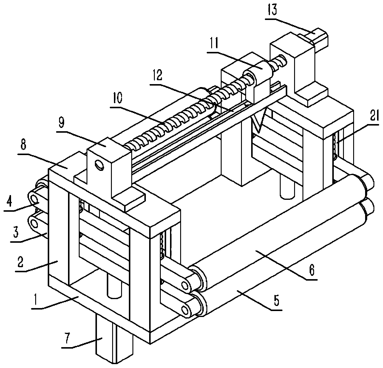
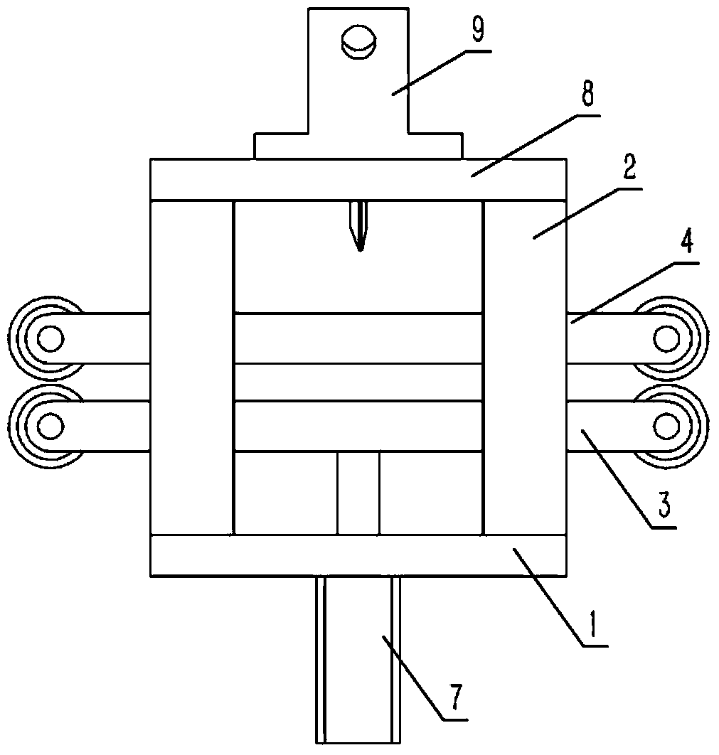
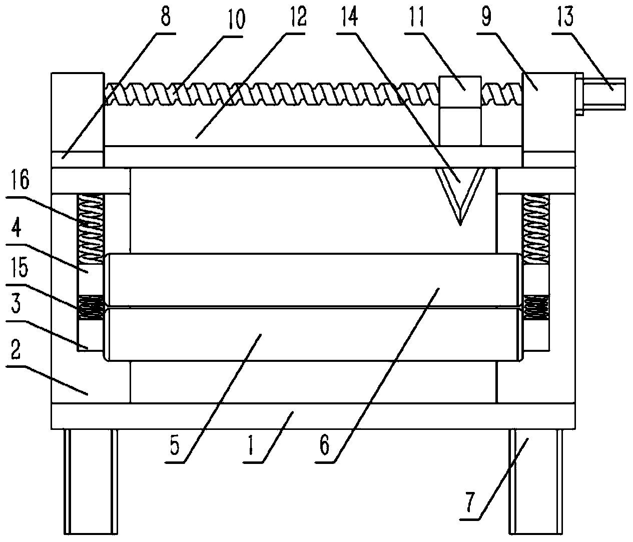
[0018] Example: see Figures 1 to 4 As shown, a textile machine cloth cutting device includes a base plate 1, four columns 2 are fixed on the base plate 1, and the four columns 2 are distributed on the front and rear sides of the base plate 1, and the columns 2 on the front and rear sides of the base plate 1 are all A crossbeam 8 is fixed, a lower connecting rod 3 and an upper connecting rod 4 are sleeved on the uprights 2 on the front and rear sides of the bottom plate 1, the two ends of the lower connecting rod 3 are respectively hinged with the lower guide roller 5, and the two ends of the upper connecting rod 4 The upper guide rollers 6 are respectively hinged, and a compression spring 15 is arranged between the upper connecting rod 4 and the lower connecting rod 3. The two ends of the compression spring 15 are respectively pressed against the upper connecting rod 4 and the lower connecting rod 3. The bottom plate A cylinder 7 is fixed on the lower end surface of the cylin...


PUM


Abstract

The invention discloses a cloth cutting device of a textile machine. The cloth cutting device of the textile machine comprises an upper reed beam, a lower reed beam, upright columns and reed teeth of a steel reed, wherein the reed teeth are uniformly distributed between the upper reed beam and the lower reed beam; linear guide rails are fixed on the upper end surface of the upper reed beam and the lower end surface of the lower reed beam and are sleeved with linear bearings; the linear bearings are fixed on the inner bottom surface of an n-shaped bracket; a clamping strip is fixedly connected to the inner side wall of the bracket through a bolt; the bolt is sleeved with a rubber strip; two side surfaces of the rubber strip are respectively propped against the clamping strip and the bracket; the end surface of one side of the rubber strip is propped against the inner end surface of the upper reed beam or the lower reed beam, and the other end of the rubber strip is exposed from the bottom surface of the bracket. According to the cloth cutting device of the textile machine, contact between a reeding cutter and the reed beams of the steel reed is avoided, and meanwhile, abrasion of the reeding cutter can be reduced due to frictional contact between the reeding cutter and the rubber strip, so that the abrasion of the reeding cutter and the steel reed is reduced, and the service lives of the reeding cutter and the steel reed are prolonged.

Description

Technical field: [0001] The invention relates to the technical field of textile machinery, and more specifically relates to a cloth cutting device for a textile machine. Background technique: [0002] At present, the fabric processed and formed by the textile loom is stored and transported in rolls, so that the winding device is used to rewind the fabric, but when the roll on the winding device is full, it needs to be replaced with a new roll, so that The fabric in the process is cut, but now the fabric cutting method is generally manual cutting with scissors, or cutting with a large cutter. Manual cutting increases the labor intensity of the operator. At the same time, the cut of the cloth cut by hand is generally Uneven, thus affecting the quality of the cloth roll, and using a cutter to cut with one knife sometimes cuts across the board continuously, and needs to be cut several times, so that the incision of the cloth becomes hairy, which affects the quality of the cloth ...

Claims


Application Information

Patent Timeline
Patent Type & Authority Applications(China)
IPC IPC(8): B65H19/26
Inventor 王锦江
Owner 苏州盛泽科技创业园发展有限公司
Learn More