
Storage rack device capable of storing and transmitting rolled materials

A material and roll-type technology, applied in the field of roll-type material storage and transmission devices, can solve the problems of customer dissatisfaction, inconvenience in viewing and selection of roll-type materials, low operation efficiency, etc., so as to reduce labor costs and labor intensity. , Reduce the effect of conveying operators

Active Publication Date: 2014-07-30
HUNAN PALETTE GARMENT
View PDF7 Cites 4 Cited by
  • Summary
  • Abstract
  • Description
  • Claims
  • Application Information

AI Technical Summary

Problems solved by technology

[0003]1. As a result of the removal of roll material from a stockpiling site or from storage racks and the replacement of unused material, and display or replacement The operation of roll materials is all done by manual operation, which is not only low in efficiency and cumbersome in process, but also labor intensive
[0004]2. It is not convenient for customers to check and select roll materials by stacking or storing roll materials on the storage rack. Selection often requires repeated flipping, searching and conveying of roll materials. For example, when providing services for customers with a small number of custom-made garments or custom-made garments, it is often necessary to repeatedly flip, search, and roll materials of different colors or textures. Or take out and put back the roll-type leather material, not only the time required for the selection process is long, the efficiency is low and the labor intensity is high, and sometimes it will cause customer dissatisfaction, affect customer satisfaction with the enterprise, and affect the operation of the enterprise efficiency

Method used


Image

  • Storage rack device capable of storing and transmitting rolled materials
  • Storage rack device capable of storing and transmitting rolled materials
  • Storage rack device capable of storing and transmitting rolled materials

Examples


Embodiment Construction

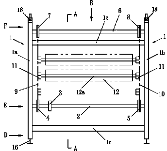
[0033] A bracket 1 is provided, and the bracket 1 includes a first side frame 1a and a second side frame 1b respectively located on both sides, see figure 1 ; A number of connecting rods 1c are provided between the first side frame 1a and the second side frame 1b to form a frame-like overall structure of the bracket 1 .

[0034] Provided with drive shaft 2, see figure 1 , both ends of the drive shaft 2 are respectively connected to the first side frame 1a and the second side frame 1b; Image 6 It shows a structural form in which one end of the transmission shaft 2 is connected to the first side frame 1a, that is, the connection between the shaft end of the transmission shaft 2 and the first side frame 1a is realized through the bearing support 1d, and the other end of the transmission shaft 2 is connected to the second side frame 1b's connection structure with Image 6 The same as shown; the connection structure between the two ends of the transmission shaft 2 and the side...


PUM


Abstract

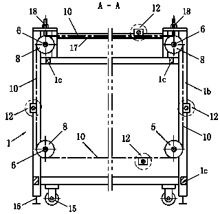
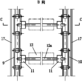
The invention discloses a storage rack device capable of storing and transmitting rolled materials. A support (1) comprises a first side frame (1a) and a second side frame (1b) which are respectively positioned on two sides; two ends of a drive shaft (2) are respectively connected to the first side frame and the second side frame, and a driving wheel (3), a first driving chain wheel (4) and a second driving chain wheel (5) are arranged on the drive shaft (2); a first driven chain wheel (7) and a second driven chain wheel (8) are arranged on the driven shaft (6); a first chain (9) is arranged on the first driving chain wheel and the first driven chain wheel, and a second chain (10) is arranged on the second driving chain wheel and the second driven chain wheel; a plurality of clamping seats, which are symmetrical and are used for installing and supporting the rolled materials, are arranged on the first chain and the second chain; elastic pressing pieces acting on the outer surfaces of the rolled materials are arranged on the first chain and the second chain. According to the storage rack device, a plurality of rolled materials can be stored, and the stored rolled materials can be transmitted to a cutting workbench or a corresponding outwards shown part through operation of the driving wheel.

Description

Technical field: [0001] The invention relates to a storage and transmission device for roll materials, in particular to a storage and transmission device for roll materials such as cloth, leather, film and paper. Background technique [0002] When storing thin-layer materials such as cloth, leather, film, paper, etc., many methods are used to wind them on the mandrel and store them in roll form, or for display, or for cutting. At present, the methods of storing or displaying roll materials include stacking them in a certain place or placing them on storage racks. The storage method of stacking or placing on the storage rack is adopted. When cutting is required, it is necessary to manually find the required roll materials from the stacking place or from the storage rack, and then transport them to the cutting workbench. After the cutting operation is completed, it is necessary to manually transport the unused roll materials to the original storage place or re-place them on t...

Claims


Application Information

Patent Timeline
Patent Type & Authority Applications(China)
IPC IPC(8): B65G1/04B65G1/14
Inventor 龚水山
Owner HUNAN PALETTE GARMENT
Learn More