
Venous transfusion device with driving plate type flow regulation device

The technology of a flow regulating device and an infusion set, which is applied in the field of medical devices, can solve the problems of changing dripping speed, high technical requirements for operation and high cost.

Inactive Publication Date: 2014-07-30
SHANDONG JIANZHU UNIV
View PDF9 Cites 6 Cited by
  • Summary
  • Abstract
  • Description
  • Claims
  • Application Information

AI Technical Summary

Problems solved by technology

[0002] At present, when medical staff give injection therapy to wounded and sick patients, they usually use manual timing counting method to adjust the drip rate. Using this method to control the drip rate is neither scientific nor safe.
In daily life, it often occurs that the infusion rate is too fast due to the patient's own adjustment of the drip rate, or the infusion is not processed in time after the infusion is completed, the infusion blockage, etc., resulting in serious consequences. In the form of inclined rollers, its structure is simple and the manufacturing cost is low. However, during the use of this infusion regulator, it is easy to cause deformation of the infusion tube, displacement of the roller, slipping, etc., resulting in changes in drip speed, and the adjustment wheel is not easy to fix stably. Location
[0003] Patents ZL03213959.4, ZL00267516.1, and ZL00136881.8 all use sensors to measure and display the number of drops, and the motor drives the control mechanism to adjust the flow rate. The system is complicated and the cost is high
Patent ZL98200544.X proposes a device for manually operating a plunger pump to control the pressure plate to squeeze the infusion tube to adjust the flow rate. This device has high requirements for operating technology and also requires manual counting and flow measurement.

Method used


Image

  • Venous transfusion device with driving plate type flow regulation device
  • Venous transfusion device with driving plate type flow regulation device
  • Venous transfusion device with driving plate type flow regulation device

Examples


Embodiment Construction

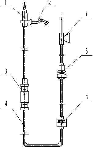
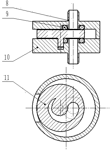
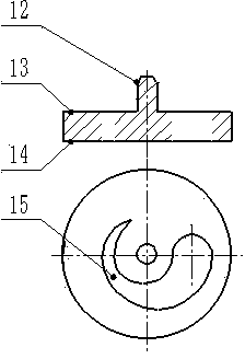
[0013] The present invention is achieved through the following technical proposals: an intravenous infusion set with a dial flow regulating device is composed of an infusion plug 1, an air inlet pipe 2, a Murphy's drip pot 3, an infusion tube 4, a dial flow regulating device 5, The filter 6 and the intravenous infusion needle 7 are composed of, and it is characterized in that: a dial flow regulating device 5 is set between the Murphy's drip pot 3 and the filter 6 to replace the traditional flow regulating device, the dial flow regulating device 5 The front and rear ends are connected with the infusion tube 4. The dial flow regulating device 5 is composed of an upper cover 8, a sealing ring 9, a lower cover 10, and a dial 11. The lower part of the upper cover 8 is hollow to place the dial 11. The lower end of the upper cover 8 has an opening 20. From the opening 20, the dial 11 can be turned to adjust the infusion flow. The inner surface 16 of the upper cover 8 is in clearance ...


PUM


Abstract

The invention discloses a venous transfusion device with a driving plate type flow regulation device. The venous transfusion device comprises a transfusion plug, an intake tube, a Murphy's drip cup, an infusion tube, the driving plate type flow regulation device, a filter and a venous infusion needle, and is characterized in that the driving plate type flow regulation device is arranged between the Murphy's drip cup and the filter; the driving plate type flow regulation device comprises an upper cover, a seal ring, a lower cover and a driving plate; the driving plate is located between the upper cover and the lower cover; a cylinder at the lower part of the driving plate is inserted in a blind hole of the lower cover; the driving plate can rotate around a center shaft of the cylinder, so as to change the superposed area between a crescent-shaped through hole slot in the middle of the driving plate and an upper cover hole. The venous transfusion device can regulate transfusion flow and is accurate in regulation, simple in structure, and convenient to operate.

Description

technical field [0001] The invention relates to a medical instrument for clinical infusion, in particular to an intravenous infusion set with a dial flow regulating device. Background technique [0002] At present, when medical personnel are doing injection therapy for wounded and sick patients, they usually use manual timing counting method to adjust the drip rate. It is unscientific and unsafe to use this method to control the drip rate. In daily life, it often occurs that the infusion rate is too fast due to the patient's own adjustment of the drip rate, or the infusion is not processed in time after the infusion is completed, the infusion blockage, etc., resulting in serious consequences. In the form of inclined rollers, its structure is simple and the manufacturing cost is low. However, during the use of this infusion regulator, it is easy to cause deformation of the infusion tube, displacement of the roller, slipping, etc., resulting in changes in drip speed, and the a...

Claims


Application Information

Patent Timeline
IPC IPC(8): A61M5/175
Inventor 王晓伟于艳杰滕培春
Owner SHANDONG JIANZHU UNIV
Learn More