Stepping switch with vacuum switching tubes

A technology of vacuum switching and tap changer, applied in electrical switches, high-voltage/high-current switches, inductors, etc., which can solve the problems of large size determination, increased power consumption, and electrical uncertainty of power transformers

Inactive Publication Date: 2014-07-23
MASCHFAB REINHAUSEN GEBR SCHEUBECK GMBH & CO KG
View PDF6 Cites 6 Cited by
  • Summary
  • Abstract
  • Description
  • Claims
  • Application Information

AI Technical Summary

Problems solved by technology

In total, however, this entails a significantly increased force consumption for the actuation of the vacuum switching tube and thereby a greater dimensioning of the individual components, which in turn is associated with significant disadvantages from a design and cost point of view.
As mentioned, since the contact force of the contact surfaces of the vacuum switch tubes is limited to the spring force of the installed spring, a brief lifting of the contact surfaces of the vacuum switch tubes can also occur during short-circuit loads and thus lead to electric shocks in the power transformer. uncertain state

Method used


Image

  • Stepping switch with vacuum switching tubes

Examples


Embodiment Construction

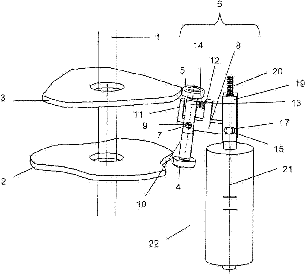
[0018] For clarity reasons, below in figure 1 Only those components of the tap changer with vacuum switching tube according to the invention which are relevant to the invention are shown and described in the diagram. Descriptions and illustrations of features known per se and components not relevant to the essence of the invention are omitted. Correspondingly, figure 1 A switching shaft 1 is shown, which is driven by a likewise not shown spring accumulator and on which two parallel, spaced apart, off-circular cam disks 2 and 3 are arranged in a non-rotatable manner. Namely a first cam disc 2 and a second cam disc 3 . The surrounding contours of the two cam disks 2 and 3 are arranged on the shifting shaft 1 substantially star-shaped in the illustrated embodiment, but pointing oppositely by 180°. The number of cam disks used and their surrounding contour depend on the switching sequence on which the tap-changer is based and the vacuum switching tubes required for this per pha...


PUM


Abstract

The invention relates to a stepping switch with vacuum switching tubes (22) according to the preamble of the first claim. According to the invention, the general inventive concept consists in providing a second cam disc (3) which is rotationally fixed to the driveshaft (1) in addition to the first cam disc (2) which is rotationally fixed to the driveshaft (1) and which is known from the prior art for applying the force of the opening stroke of the contact system of the vacuum switching tubes (22). The second cam disc exerts a sufficiently high closing force onto the movable follower of the vacuum switching tubes (22) via a spring-lever system provided on the rocker arm arrangement (6) even in the event of a short-circuit stress and additionally allows a tolerance compensation of the contact system.

Description

technical field [0001] The invention relates to a tap changer with a vacuum switching tube according to the preamble of claim 1 . Background technique [0002] Tap changers have been used in large numbers all over the world for the uninterrupted changeover between different winding taps of tapped transformers for many years. Such a tap changer usually includes a selector for powerlessly selecting the corresponding winding tap of the tap changer to which it should be switched, and a switch for actually switching from the switched on winding tap to the new preselected winding tap. load transfer switch. The jumpy switching is usually carried out by means of an energy store, when the switching shaft rotates rapidly when the energy store is activated. A load changeover switch also usually has a switching contact and a resistance contact. The switch contacts are used here for the direct connection of the corresponding winding taps and load lead-offs, for short-term connections,...

Claims


Application Information

Patent Timeline
Patent Type & Authority Applications(China)
IPC IPC(8): H01H3/42H01H9/00
CPCH01H3/42H01H9/0027H01H9/0038H01F29/04H01H33/666H01H2033/6667
Inventor K·赫普夫尔S·弗雷德
Owner MASCHFAB REINHAUSEN GEBR SCHEUBECK GMBH & CO KG
Why Eureka
Try Eureka