
A bidirectional sliding device suitable for civil engineering space loading test

A space loading and civil engineering technology, which is applied in the direction of measuring devices, testing of machines/structural components, instruments, etc., can solve problems such as test errors, hindering the development of space structure tests, and being unable to follow in two directions, so as to achieve convenient operation and installation , matching the effect of good

Active Publication Date: 2016-08-17
TONGJI UNIV +1
View PDF6 Cites 0 Cited by
  • Summary
  • Abstract
  • Description
  • Claims
  • Application Information

AI Technical Summary

Problems solved by technology

At the level of the existing device, the actuator applying the axial force can only be directly hinged on the reaction frame or at most can achieve one-way follow-up sliding, and cannot follow-up in two directions; under this condition, with the deformation of the test piece, the shaft The axial force will not be kept in the vertical direction, and will generate components in the horizontal direction, and the magnitude of the vertical force in the vertical direction will also change, resulting in serious experimental errors and hindering the development of space structure tests

Method used


Image

  • A bidirectional sliding device suitable for civil engineering space loading test
  • A bidirectional sliding device suitable for civil engineering space loading test
  • A bidirectional sliding device suitable for civil engineering space loading test

Examples


Embodiment Construction

[0025] The present invention will be further described below in conjunction with drawings and embodiments.

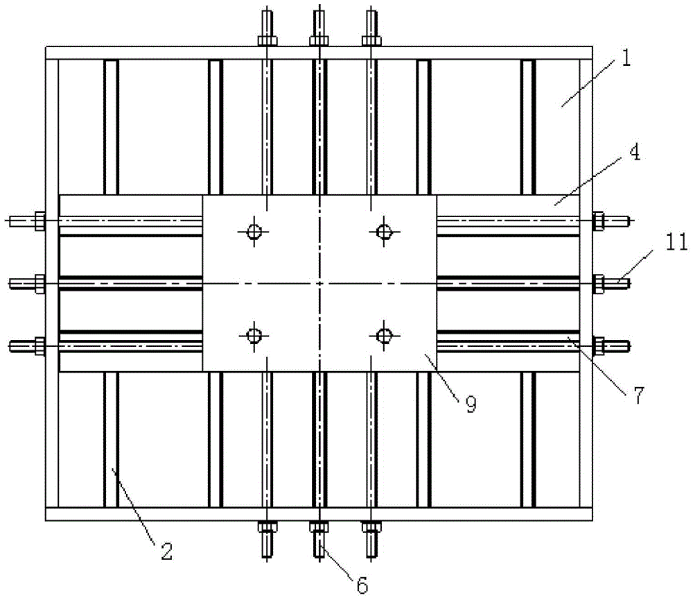
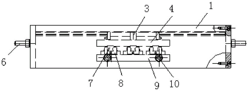
[0026] Such as Figure 1 to Figure 3 As shown, a two-way sliding device suitable for civil engineering space loading test, from top to bottom includes connecting support 1, the upper sliding structure fixedly installed under the connecting support, located below the upper sliding structure and connected to the upper The sliding structure is a lower layer sliding structure connected by sliding, the lower layer sliding structure is used to connect the actuator, and the sliding direction of the upper layer sliding structure is perpendicular to the sliding direction of the lower layer sliding structure.

[0027] The connecting support 1 is fixed on the reaction frame or the trough, the upper sliding structure is fixedly connected with the connecting supporting 1 to form a stable sliding plane, and the lower sliding structure is connected to the actuator so that the actuator...


PUM


Abstract

A bidirectional sliding device suitable for a civil engineering space loading test comprises a connecting support, an upper layer sliding and moving structure and a lower layer sliding and moving structure from top to bottom, wherein the upper layer sliding and moving structure is fixedly mounted below the connecting support, the lower layer sliding and moving structure is located below the upper layer sliding and moving structure and is connected with the upper layer siding and moving structure, and the sliding and moving direction of the upper layer sliding and moving structure is perpendicular to that of the lower layer sliding and moving structure. The connecting support is fixed to a reaction force frame or a ground groove, an actuator is connected with one face of the lower layer sliding and moving structure so that the actuator can move in the direction of a lower layer linear sliding guide rail, and the other face of the lower layer sliding and moving structure is connected with the upper layer sliding and moving structure so that the lower layer sliding and moving structure and the actuator can move in the direction of an upper layer linear sliding guide rail. According to the bidirectional sliding device suitable for the civil engineering space loading test, the free sliding of the actuator along with the displacement of a loading point of a test part in any direction can be achieved when the actuator connected with the bidirectional sliding device applies loads to the test part; meanwhile, the loading direction of the actuator is unchanged all the time, and additional constraining force is not generated.

Description

technical field [0001] The invention belongs to the field of civil engineering structure test, relates to the research of various loading tests on the structure test piece, and is especially suitable for the test that requires space follow-up of the load when the test piece is loaded in space. Background technique [0002] In order to study the spatial performance of the structure, it is often necessary to load the structure in three directions, including axial load and two-way horizontal load. When loading, in order to ensure the accuracy of two-way horizontal load measurement, it is required that the axial direction, it can move freely with the loading point, and does not produce restraint reaction force. At the level of the existing device, the actuator applying the axial force can only be directly hinged on the reaction frame or at most can achieve one-way follow-up sliding, and cannot follow-up in two directions; under this condition, with the deformation of the test pi...

Claims


Application Information

Patent Timeline
Patent Type & Authority Patents(China)
IPC IPC(8): G01M99/00
Inventor 陈以一赵宪忠钟绵新程欣
Owner TONGJI UNIV
Learn More