Tensioning device for end beam of crane

A technology of tensioning device and crane, which is applied in the direction of transportation and packaging, load hanging components, supporting structures, etc. It can solve the problems of large or small distance between the two side plates, reduce work efficiency, and low accuracy, and achieve adjustment The effect of high accuracy, improved work efficiency, and convenient adjustment process

Active Publication Date: 2014-07-23
宁波市凹凸重工有限公司
View PDF6 Cites 3 Cited by
  • Summary
  • Abstract
  • Description
  • Claims
  • Application Information

AI Technical Summary

Problems solved by technology

The following methods have the following disadvantages: the ladder frame needs to be tapped during the adjustment process, which not only takes time and effort, but also produces a lot of noise, which is more harmful to the environment; the accuracy of the adjustment is not high, and the distance between the two side plates is prone to be too large or The phenomenon of being too small requires repeated adjustments to meet the requirements, thereby reducing work efficiency

Method used


Image

  • Tensioning device for end beam of crane
  • Tensioning device for end beam of crane
  • Tensioning device for end beam of crane

Examples


Embodiment Construction

[0023] The present invention will be further described below in conjunction with the accompanying drawings and specific embodiments.

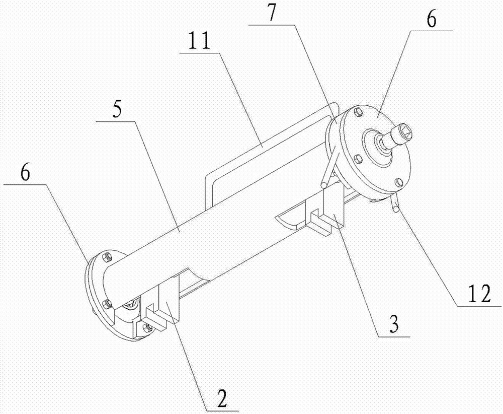
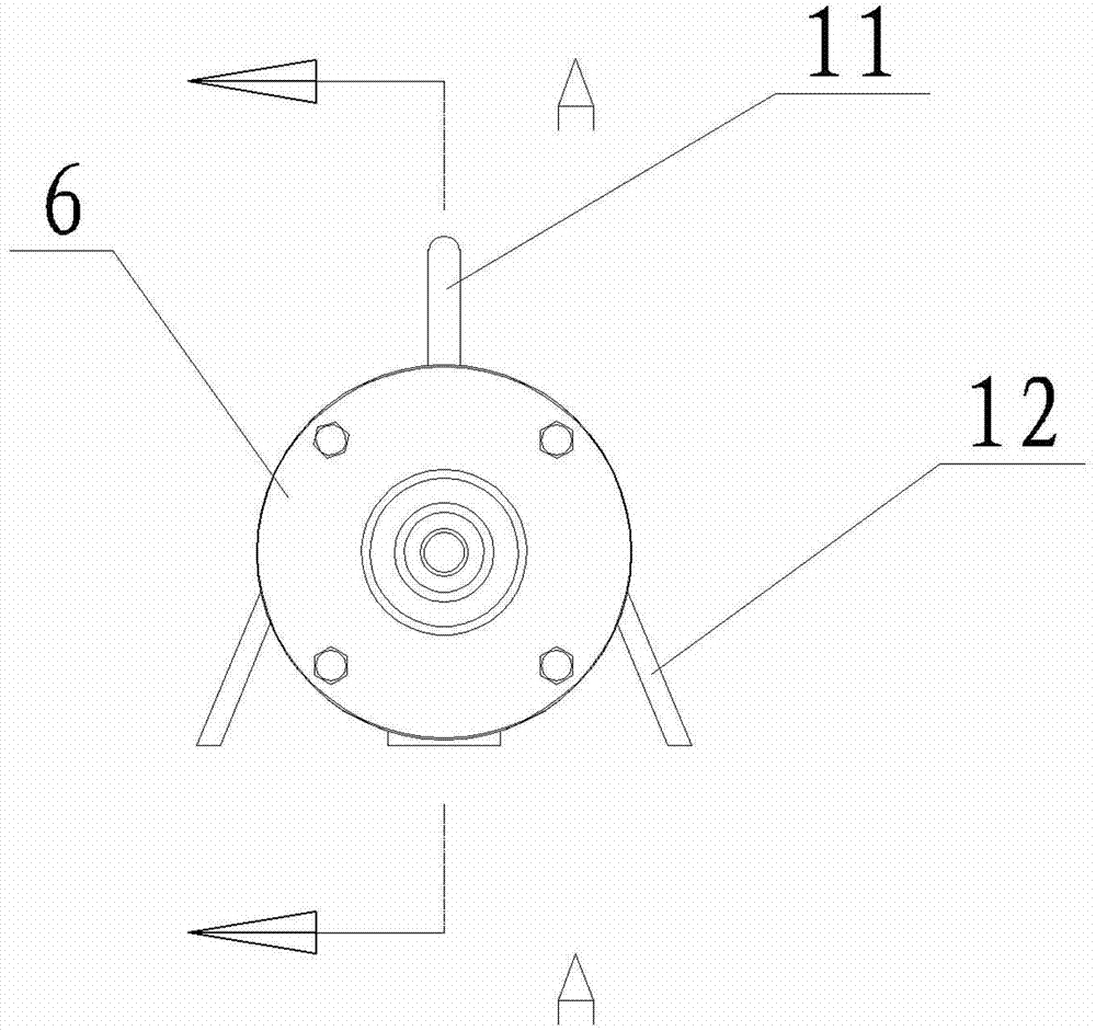
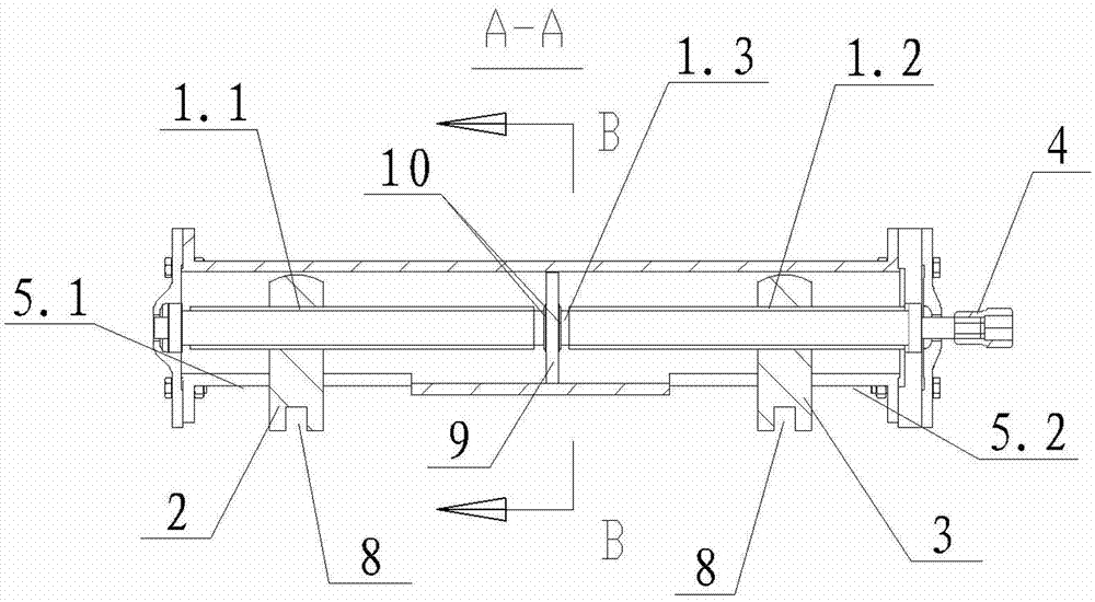
[0024] see figure 1 , figure 2 , image 3 and Figure 4 As shown, the crane end beam tensioning device of the present invention includes a support frame, a two-way screw rod 1 , a left clamping block 2 and a right clamping block 3 . The two-way screw 1 is provided with a left thread section 1.1 and a right thread section 1.2, and the thread direction of the left thread section 1.1 is opposite to that of the right thread section 1.2, that is, when the left thread section 1.1 is left-handed , the right-hand thread segment 1.2 is right-handed; when the left-hand thread segment 1.1 is right-handed, the right-hand thread segment 1.2 is left-handed. Both ends of the two-way screw 1 are respectively supported on the support frame. The left clamping block 2 and the right clamping block 3 are threadedly mounted on the left threaded section 1.1 and...


PUM


Abstract

The invention discloses a tensioning device for an end beam of a crane. The tensioning device comprises a support frame, a bidirectional screw rod, a left clamp block and a right clamp block, wherein the bidirectional screw rod is provided with a left threaded section and a right threaded section, and the thread direction of the left threaded section is opposite to that of the right threaded section; two ends of the bidirectional screw rod are respectively supported on the support frame; the left clamp block and the right clamp block are respectively screwed on the left threaded section and right threaded section of the bidirectional screw rod; the left clamp block and the right clamp block are circumferentially limited by the support frame; the left clamp block and the right clamp block move close to or away from each other when being driven by the clockwise rotation or anticlockwise rotation of the bidirectional screw rod; clamping parts for being clamped on side plates of the end beam of the crane are arranged on the left clamp block and the right clamp block; a connecting head for connecting the driving device is arranged at one end of the bidirectional screw rod. By utilizing the tensioning device, the interval between the two side plates of the end beam of the crane can be accurately regulated, the time and the labor are saved, and no noise is generated.

Description

technical field [0001] The invention relates to a crane end beam tensioning device. Background technique [0002] The crane end girders are arranged on both sides of the main girder of the crane cart, and are used to carry the main girder. The shape of the cross section of the end beam of the crane is U-shaped. During production, the inner side of the end beam needs to be welded with a stiffener, that is, the stiffener is welded between the two side plates of the end beam. The stiffener is used to increase the strength of the end beam. stability. However, when installing the stiffener, it is often encountered that the length of the stiffener does not match the length of the distance between the two sides of the end beam, that is, the length of the stiffener is longer than the length of the distance between the two sides of the end beam If it is too large, the stiffener cannot be installed into the end beam; if the length of the stiffener is smaller than the distance betwee...

Claims


Application Information

Patent Timeline
IPC IPC(8): B66C6/00
Inventor 朱良军
Owner 宁波市凹凸重工有限公司
Why Eureka
Try Eureka