
Energy-saving and environment-friendly vibrating conveyer

A vibrating conveyor, energy-saving and environment-friendly technology, applied in the field of conveyors, can solve the problems of increased vibration weight, spilling in the air, short service life, etc., and achieve the reduction of requirements, friction reduction, and lower probability of secondary damage Effect

Inactive Publication Date: 2014-07-23
新乡市威盛机械设备有限公司
View PDF6 Cites 0 Cited by
  • Summary
  • Abstract
  • Description
  • Claims
  • Application Information

AI Technical Summary

Problems solved by technology

Its shortcoming is, the rocker arm connection device that the structure of prior art adopts, and rocker arm only has support guiding function, and its rocker arm is passive work, and also needs to use support plate, copper sleeve, pin as connecting part, in During use, the copper sleeve and the pin shaft wear quickly, the service life is short, and the maintenance rate is high; the transmission of the prior art structure uses an eccentric crankshaft, and if the eccentric part is damaged during use, it needs to be replaced as a whole, increasing the cost. The production cost is increased; moreover, the transmission device is designed under the feed end, and the design shortcomings will lead to the longer the conveyor length, the greater the overall strength of the tank body, so the weight of the vibration will increase accordingly, and the power demand will increase relatively. Large; because the trough of the conveyor with this structure is open, during the process of conveying materials, the materials are thrown up, and the powdery part of the materials will inevitably be scattered in the air, causing the surrounding environment to be polluted

Method used


Image

  • Energy-saving and environment-friendly vibrating conveyer
  • Energy-saving and environment-friendly vibrating conveyer
  • Energy-saving and environment-friendly vibrating conveyer

Examples


Embodiment Construction

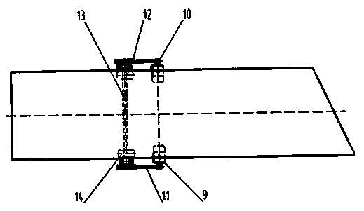
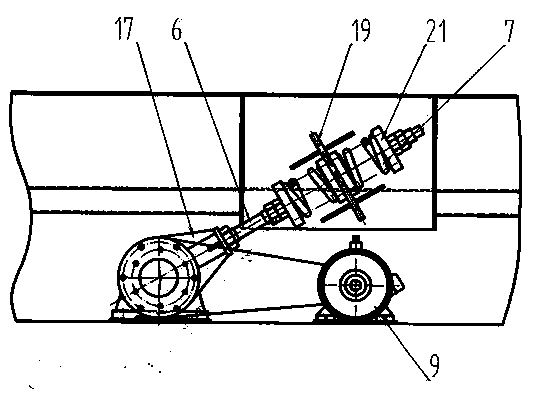
[0009] Embodiments are described in detail in conjunction with the above accompanying drawings, as figure 1 As shown, the tank body 2 is movably connected with the base 1 through the vibration damping support spring 3 and the plate guide support spring 4. The plate guide support spring and the vibration damping spring support spring are arranged in the lower part of the tank body in groups. The number of springs in each group It can be set according to the width and length of the tank (parameter weight). The angle between the centerlines of each group is 90 degrees. It is connected with the base 1 and the tank 2 by bolts and the pressure plate 36. The vibration-damping support spring Using a spiral steel pressure spring, the tank body can be opened or closed. One end of the tank body is the feed end 8, and the other end is the discharge end 20. The transmission device 5 is fixedly connected to the base 1, and the transmission device adopts What is more is motor 9, and describe...


PUM


Abstract

The invention discloses an energy-saving and environment-friendly vibrating conveyer which comprises a groove body and a base. The groove body is movably connected with the base through a vibration attenuation supporting spring and a plate guide supporting spring. Motors are installed below the middle section of the groove body. The motors are in key connection with large belt wheels, and the large belt wheels are installed at the two ends of a main shaft. Screw rods are symmetrically arranged at the left portion and the right portion of the lower portion of the groove body and are connected with bearing housings at the two ends of the main shaft, compression is conducted by a compressing cover to form elastic connection through a spring support, and the spring support is fixedly connected with the groove body. According to the technical scheme, the plate guide supporting spring and a power spring can generate stronger bounce under the power effect, and a transmission gear can more efficiently provide power for the conveyer through the bounce, so that the requirement for prime power in the working process is reduced, and the energy-saving effect is achieved. Compared with a traditional vibration conveyer, the vibration amplitude is larger, the vibration frequency is smaller, the vibration amplitude (ranging from 18 mm to 26 mm) of the energy-saving and environment-friendly vibrating conveyer is one third that of the traditional vibration conveyer, and friction between materials and the groove body is reduced to the maximum degree.

Description

[0001] Technical field: [0002] The invention relates to a conveyor, which is especially suitable for sugar manufacturing engineering. After the sugar is crystallized, it is separated by a secreting machine, and then the piles of sugar separated by the secreting machine are dispersed by its vibrating conveyor, so that the sugar can evenly enter the lower An energy-saving and environment-friendly vibrating conveyor for the first process. Background technique: [0003] The "vibrating conveyor" disclosed by the National Patent Office, application number 200710132141.9, includes a base, a tank body, a transmission device, a swing arm, a spring, one end of the tank body is the feeding end, and the other end is the discharge end, the transmission device and the tank body There is a fixed connection between them, and the tank body is movably linked with the base through a swing arm and a spring. The transmission device includes a motor, a small pulley, a large pulley, a belt, ...

Claims


Application Information

Patent Timeline
Patent Type & Authority Applications(China)
IPC IPC(8): B65G27/04B65G27/12
Inventor 刘惠平王延伟魏河成王治琦
Owner 新乡市威盛机械设备有限公司
Learn More