
A special band sawing machine for bevel sawing of reel shaft and its use method

A reel shaft and band sawing machine technology, applied in the field of sawing machines, can solve the problems of wasting raw materials, long processing time, and difficult positioning, and achieve the effects of ensuring angular accuracy, ensuring mutual vertical accuracy, and improving the use range

Active Publication Date: 2016-06-01
ZHE JIANG CHENLONG SAWING MACHINE CO LTD
View PDF6 Cites 0 Cited by
  • Summary
  • Abstract
  • Description
  • Claims
  • Application Information

AI Technical Summary

Problems solved by technology

[0002] At present, the milling process is generally used to form the inclined surface of the drum shaft. Due to the limitation of the milling machine's own structure and milling angle, this process not only takes a long time, but also makes it difficult to locate. At the same time, a large amount of iron filings will be formed during the milling machine process. These wastes are difficult to recycle, not only waste raw materials, but also pollute the environment

Method used


Image

  • A special band sawing machine for bevel sawing of reel shaft and its use method
  • A special band sawing machine for bevel sawing of reel shaft and its use method
  • A special band sawing machine for bevel sawing of reel shaft and its use method

Examples


Embodiment Construction

[0027] The present invention will be described in further detail below in conjunction with the accompanying drawings, but it is not intended to limit the protection scope of the present invention.

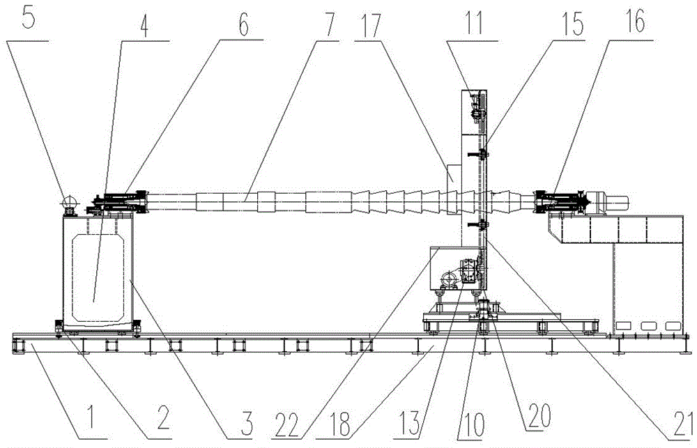
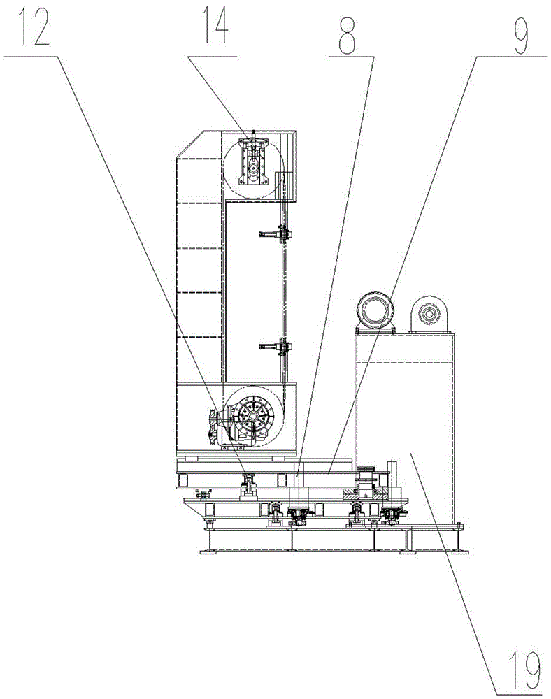
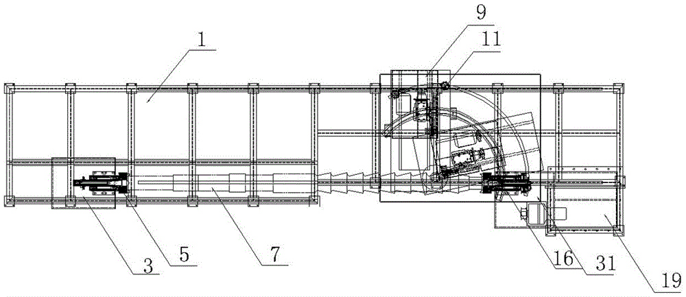
[0028] Such as Figure 1-3 As shown, a special band sawing machine for reel shaft bevel sawing includes a base 1 and a sawing machine body arranged on the base 1. The sawing machine body includes a sawing machine base 9, a saw frame 11 arranged on the sawing machine base 9, and a saw frame set on the saw frame. The main transmission system 13 on the saw frame 11, the saw frame hydraulic station 17, the cooling system 18 and the electrical system 19 arranged on one side of the saw frame 11, the sawing machine base 9 is slidably connected to the base 1, and the base 1 is provided with supporting workpieces at both ends. Matching fixed support seat 31 and movable support seat 3, the fixed support seat 31 and the movable support seat 3 are arranged on both sides of the sawing machine b...


PUM


Abstract

The invention discloses a special band sawing machine for sawing a drum shaft inclined plane. The special band sawing machine comprises a base and a sawing machine body arranged on the base. The sawing machine body comprises a sawing machine base, a sawing frame arranged on the sawing machine base, a main drive system arranged on the sawing frame, a sawing frame hydraulic station arranged on the sawing frame, a cooling system and an electric system, wherein the cooling system and the electric system are arranged on one side of the sawing frame. A fixed supporting base and a movable supporting base are arranged on the base and used for supporting the two ends of a workpiece to be mutually matched. The fixed supporting base and the movable supporting base are arranged on the two sides of the sawing machine body, the height of the fixed supporting base and the movable supporting base is matched with the sawing height of the sawing frame, and a sawing machine rotating device and a locking oil cylinder are arranged on the sawing machine base and used for controlling the sawing machine to rotate. A movable supporting base rotation locking device is arranged on the movable supporting base and used for supporting one end of the workpiece. A fixed supporting base rotation locking device and a driving device are arranged on the fixed supporting base and used for supporting the other end of the workpiece. Machining time can be saved, production efficiency can be improved, and the utilization rate of material can be increased.

Description

technical field [0001] The invention relates to a sawing machine, in particular to a special band sawing machine for bevel sawing of a reel shaft and a use method thereof. Background technique [0002] At present, the milling process is generally used to form the inclined surface of the drum shaft. Due to the limitation of the milling machine's own structure and milling angle, this process not only takes a long time, but also makes it difficult to locate. At the same time, a large amount of iron filings will be formed during the milling machine process. These wastes are difficult to recycle, which not only wastes raw materials, but also pollutes the environment. Contents of the invention [0003] In order to solve the defects and deficiencies of the above-mentioned prior art, the present invention provides a special band sawing machine for reel shaft bevel sawing that can facilitate positioning, save processing time, improve production efficiency, improve material utilizat...

Claims


Application Information

Patent Timeline
Patent Type & Authority Patents(China)
IPC IPC(8): B23D55/04B23D55/06
Inventor 丁泽林江平
Owner ZHE JIANG CHENLONG SAWING MACHINE CO LTD
Learn More