Internal burr removal mechanism for straight seam steel pipe

A technology for steel pipes and straight seams, applied in the field of burr removal mechanisms in straight seam steel pipes, can solve problems such as easy corrosion of protrusions at weld seams, reduced service life of steel pipes, and decreased fluid flow rate in pipes, so as to shorten abnormal processing time , Guaranteed performance and improved cleaning efficiency

Active Publication Date: 2016-09-07
JIANGSU LIWEI SHEARING & BENDING MACHINE
View PDF5 Cites 0 Cited by
  • Summary
  • Abstract
  • Description
  • Claims
  • Application Information

AI Technical Summary

Problems solved by technology

However, after the partial welding of the steel pipe is completed, the weld seam is directly exposed to the air. Due to the difference between the air temperature and the temperature of the weld seam itself, the weld seam will directly change from high temperature to low temperature. The strength of the steel itself reduces the stability of the steel pipe, and in severe cases it will directly cause the weld seam of the steel pipe to be de-welded; and a certain amount of burrs will be generated inside and outside the steel pipe near the weld seam during welding, which makes the flow rate of the fluid in the pipe drop when the steel pipe is in use. , and the protrusions at the weld are easily corroded, which leads to a decrease in the overall strength of the weld and reduces the service life of the steel pipe; traditional internal burr removal equipment mainly focuses on the solder residue and protrusions around the weld and the weld However, the solder residue and protrusions scattered to other parts of the inner wall of the steel pipe during welding are not cleaned thoroughly

Method used


Image

  • Internal burr removal mechanism for straight seam steel pipe
  • Internal burr removal mechanism for straight seam steel pipe
  • Internal burr removal mechanism for straight seam steel pipe

Examples


Embodiment 1

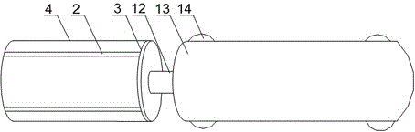
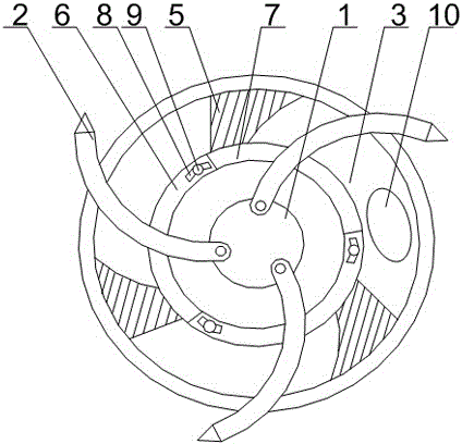
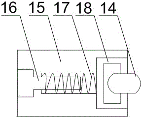
[0021] like figure 1 , figure 2 and image 3 As shown, the external burr cleaning mechanism for welded steel pipes of the present invention includes a support cylinder 13, the end of the support cylinder 13 is connected with an external mandrel, a plurality of rollers 14 are arranged on the support cylinder 13, and the support cylinder 13 A drive motor is arranged inside, and the output end 12 of the drive motor is connected to a tool. The tool includes a central shaft 1, and a plurality of arc-shaped blades 2 are arranged on the central shaft 1. The arc-shaped blades 2 are hinged with the central shaft 1 and The annular array is distributed on the outer wall of the central shaft 1, the upper and lower ends of the central shaft 1 are installed with fixed plates 3 and the arc-shaped blade 2 is arranged between the two fixed plates 3, and also includes a blade angle adjustment set between the arc-shaped blades 2 The blade angle adjustment mechanism includes a connecting rod 7...


PUM


Abstract

The invention discloses a removing mechanism for burrs in straight welded steel pipes. The removing mechanism comprises a support barrel and blade angle adjusting mechanisms. An end of the support barrel is connected with an external core rod, a plurality of rollers are arranged on the support barrel, a driving motor is arranged in the support barrel, an output end of the driving motor is connected with a cutter, the cutter comprises a center shaft, a plurality of arc-shaped blades are arranged on the center shaft, are hinged to the center shaft and are annularly arrayed and distributed on the outer wall of the center shaft, fixing plates are mounted at the upper end and the lower end of the center shaft, the arc-shaped blades are arranged between the two fixing plates, and the blade angle adjusting mechanisms are arranged among the arc-shaped blades. The removing mechanism has the advantages that the blade angle adjusting mechanisms are flexible in connection mode and simple in structure, accordingly, included angles among the arc-shaped blades and the center shaft can be quickly adjusted while the arc-shaped blades are assuredly firmly fixed, the abnormal machining time can be shortened, the efficiency can be improved when welding flux residues and protrusions on the inner walls of the steel pipes are cleaned, and the service performance of the steel pipes can be guaranteed.

Description

technical field [0001] The invention relates to an auxiliary equipment of a argon arc welding machine, in particular to a burr removal mechanism in a straight seam steel pipe. Background technique [0002] When welding steel pipes, in order to ensure a good welding effect, the welding head and the steel pipe to be welded are generally placed in a semi-closed box to facilitate the introduction of protective gas and to avoid sparks from splashing around during welding. However, after the steel pipe is partially welded, the weld is directly exposed to the air. Due to the difference between the air temperature and the temperature of the weld itself, the weld will directly change from high temperature to low temperature. During this period, the weld of the steel pipe will decrease due to the sudden change of temperature. Its own strength reduces the stability of the use of the steel pipe. In severe cases, it will directly cause the steel pipe weld to be de-welded; and a certain a...

Claims


Application Information

Patent Timeline
Patent Type & Authority Patents(China)
IPC IPC(8): B23D79/04
Inventor 陈怀之王刚聂海涛张仁友胡国波
Owner JIANGSU LIWEI SHEARING & BENDING MACHINE
Why Eureka
Try Eureka