
Hemostat

A technology of a hemostat and a liquid storage chamber, which is applied in the field of medical appliances, can solve problems such as unfavorable observation of bleeding points, bleeding, and patient discomfort, and achieve flexible structure and relative position settings, no need for professional skills, and good stability

Active Publication Date: 2014-07-16
深圳市升昊科技有限公司
View PDF6 Cites 6 Cited by
  • Summary
  • Abstract
  • Description
  • Claims
  • Application Information

AI Technical Summary

Problems solved by technology

The above-mentioned structure must also be externally connected with an air source or a liquid source, which has the same disadvantages as the above-mentioned air bag hemostat
Moreover, since the air pressure or hydraulic device is arranged vertically, the protruding surface of the hemostat is relatively high, and it is easy to collide with the outside world, resulting in compression and displacement, causing bleeding and discomfort to the patient
At the same time, the hemostat using the longitudinal platen structure is not conducive to observing the bleeding point because the air pressure or hydraulic device is arranged directly above the bleeding point.

Method used


Image

  • Hemostat
  • Hemostat
  • Hemostat

Examples


Embodiment Construction

[0027] In order to make the object, technical solution and advantages of the present invention clearer, the present invention will be further described in detail below in conjunction with the accompanying drawings and embodiments. It should be understood that the specific embodiments described here are only used to explain the present invention, not to limit the present invention.

[0028] It should be noted that when an element is referred to as being “fixed on” or “disposed on” another element, it may be directly on the other element or there may be an intervening element at the same time. When an element is referred to as being "connected to" another element, it can be directly connected to the other element or intervening elements may also be present.

[0029] It should also be noted that the orientation terms such as left, right, up, and down in this embodiment are only relative concepts or refer to the normal use state of the product, and should not be regarded as limiti...


PUM


Abstract

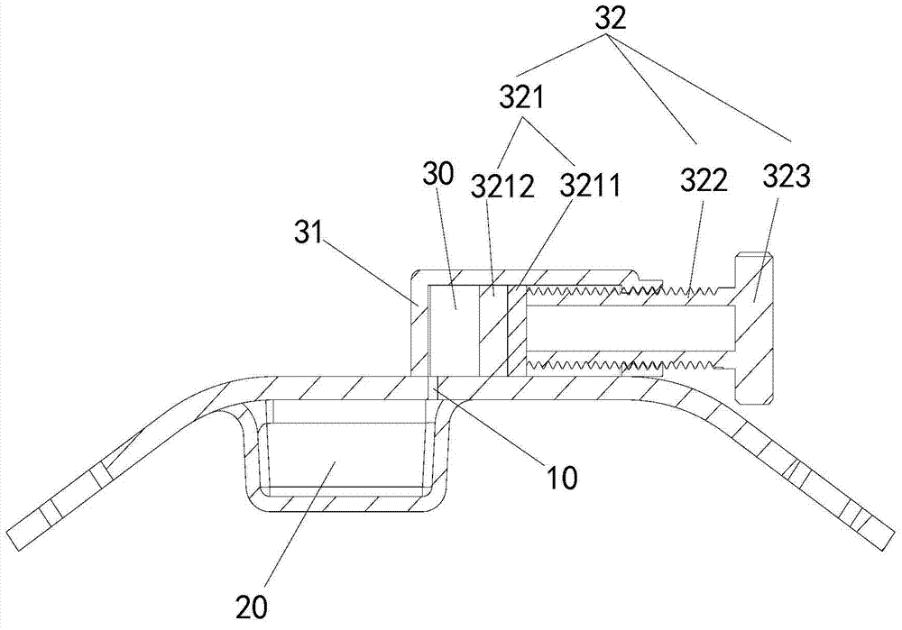
The invention is suitable for the field of medical instruments and discloses a hemostat. The hemostat comprises a compressing body and a regulating component, wherein the compressing body is provided with an inner cavity capable of containing liquid, and the effective volume of the inner cavity can be changed through the amount of the liquid in the inner cavity; the regulating component is provided with a liquid storage cavity for containing liquid, the liquid storage cavity is communicated with the inner cavity, and the regulating component is used for regulating the relative amount of liquid in the liquid storage cavity and liquid in the inner cavity so that the liquid can flow between the liquid storage cavity and the inner cavity and the pressure applied by the compressing body can be changed. According to the hemostat, because the liquid is sealed between the two cavities, a control valve is not needed to obtain the hemostat and an external liquid source is not needed further, the manufacturing cost and the using cost are effectively reduced, and the compressing force of the compressing body can be conveniently regulated. Because liquid serves as the working medium, the flow direction is easy to change, all the components can be arranged in space of the using positions easily, hidden danger caused by collision between the regulating component and other objects is avoided, the conditions of a hemorrhagic spot can be seen easily, and the hemostat is good in using effect and high in reliability.

Description

technical field [0001] The invention belongs to the field of medical appliances, in particular to a hemostat. Background technique [0002] Current hemostats, such as radial hemostats, mostly compress the bleeding point through an air bag. Its airbag is operated by an external syringe. The balloon must be connected to the syringe every time the pressure is adjusted. The operation is inconvenient and requires high experience for the operator. It is clinically required to decompress the pressure regularly to prevent radial artery complications during the hemostasis process. Therefore medical personnel need repeatedly to reduce gas with syringe, and workload is quite large. [0003] In the prior art, it is also possible to press the bleeding point by driving the pressure plate with air pressure or hydraulic pressure. The air pressure or hydraulic cylinder is arranged vertically and located directly above the pressure plate, and an air (liquid) hole or a gas (liquid) hole is...

Claims


Application Information

Patent Timeline
IPC IPC(8): A61B17/12
CPCA61B17/12A61B17/132A61B2017/12004
Inventor 黄旭明何世华保罗·鲍狄勒夏俊
Owner 深圳市升昊科技有限公司
Learn More