Lighting scene editing method and LED lighting control method
A technology for LED lamps and scenes, applied in the direction of light source, electric light source, electric light circuit layout, etc., can solve the problem that it is difficult for users to edit the lighting scene according to their needs, and achieve the effect of easy editing, satisfying editing needs, and simple operation steps.
- Summary
- Abstract
- Description
- Claims
- Application Information
AI Technical Summary
Problems solved by technology
Method used
Image


Examples
Embodiment 1
[0058] Such as figure 1 As shown, a lighting scene editing method includes the following steps:
[0059] Step S110, describing the position of each LED light emitting unit of the LED lamp.
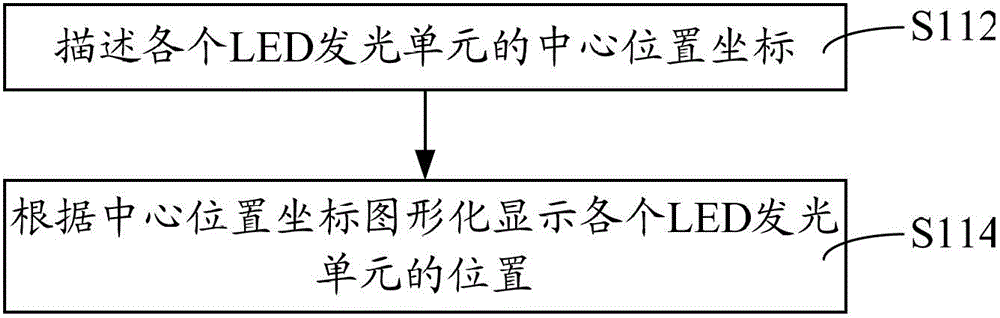
[0060] An LED lamp is selected, and the LED lamp can be an LED soft-color ceiling lamp, and the LED lamp has a plurality of LED light-emitting units. According to the arrangement and layout of multiple LED light-emitting units in the LED lamp, the computer is used to describe the position of the multiple LED light-emitting units in the LED lamp. Usually, the position of multiple LED light-emitting units in the LED lamp is expressed in the form of position coordinates in the computer . Such as figure 2 As shown, in this embodiment, step S110 includes: step 112, describing the center position coordinates of each LED light emitting unit. Since each LED light-emitting unit in an actual LED lamp has a certain volume. In order to facilitate the description of the position of each LED unit,...
Embodiment 2
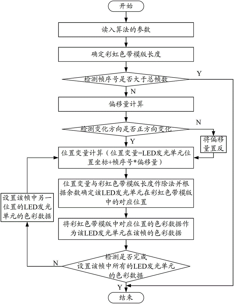
[0082] Such as Figure 5 As shown, this embodiment is basically the same as Embodiment 1, the difference is that the specific process of step S120 is as follows:
[0083] Step S122, mapping the positions of all LED lighting units to a display area of a multimedia material. When a multimedia material is selected, the computer maps the position areas of all light-emitting units to the display area of the FLASH (animation) material. The multimedia material can be animation material and / or picture material. During the mapping process, the size and angle of the multimedia material can be adjusted as required, so that the positions of all light-emitting units can be mapped to the display area of the animation material.
[0084] In step S124, the color data of the mapping positions of each LED light-emitting unit is acquired frame by frame during the playback of the multimedia material. After the mapping is completed, the multimedia material is played and the color data of th...
Embodiment 3
[0086] In this embodiment, besides the method of embodiment 1, step S120 includes: manually editing the color data of the LED light emitting unit frame by frame.
[0087] Usually, a computer is used to manually edit frame by frame to generate the color data of all LED light-emitting units. Draw pictures frame by frame on the drawing board where the positions of all LED light emitting units are graphically displayed.
PUM
 Abstract
Description
Claims
Application Information
 - R&D
- Intellectual Property
- Life Sciences
- Materials
- Tech Scout
- Unparalleled Data Quality
- Higher Quality Content
- 60% Fewer Hallucinations
Browse by: Latest US Patents, China's latest patents, Technical Efficacy Thesaurus, Application Domain, Technology Topic, Popular Technical Reports.
© 2025 PatSnap. All rights reserved.Legal|Privacy policy|Modern Slavery Act Transparency Statement|Sitemap|About US| Contact US: help@patsnap.com