
An Injection Locked Frequency Divider Structure with Automatic Frequency Calibration Function

A technology of injection locking and automatic frequency, which is applied in the direction of automatic power control and electrical components, can solve the problems of difficult control of control voltage and unstable operating frequency range of ILFD, and achieve low power consumption, good resistance, and high operating frequency. Effect

Active Publication Date: 2016-09-14
ZHEJIANG UNIV
View PDF6 Cites 0 Cited by
  • Summary
  • Abstract
  • Description
  • Claims
  • Application Information

AI Technical Summary

Problems solved by technology

[0005] In view of this, the present invention provides an injection-locked frequency division structure with an automatic frequency verification function, which is suitable for millimeter-wave frequency bands, so as to obtain the input frequency range of the actual working state, to overcome the inadequacy of the ILFD working frequency range in the prior art. Stable, control voltage V T Difficult to control issues and resistance to potential process variation

Method used


Image

  • An Injection Locked Frequency Divider Structure with Automatic Frequency Calibration Function
  • An Injection Locked Frequency Divider Structure with Automatic Frequency Calibration Function
  • An Injection Locked Frequency Divider Structure with Automatic Frequency Calibration Function

Examples


Embodiment Construction

[0024] The present invention will be described in further detail below in conjunction with the accompanying drawings and specific embodiments.

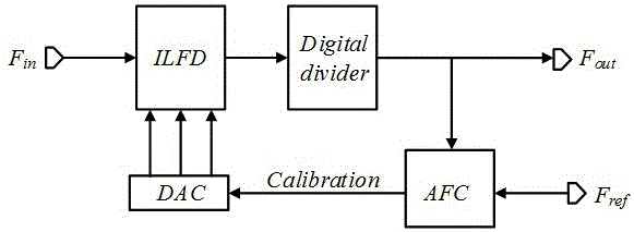
[0025] Such as figure 1 As shown, the injection-locked frequency division structure of the present invention includes the following:

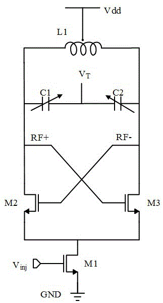
[0026] Included for receiving preset input signal F in and according to the resonant frequency to the preset input signal F in performing frequency division to generate an injection-locked frequency divider for a first frequency-divided signal;

[0027] Including a digital frequency divider for receiving the first frequency division signal and performing second frequency division to generate the second frequency division signal, the second frequency division signal is used as the preset output signal F out ;

[0028] Including for combining the received second frequency-divided signal with the reference signal F ref An automatic frequency controller that generates a digital calibration selection ...


PUM


Abstract

The invention discloses an injection locking frequency division structure with an automatic frequency verification function. The injection locking frequency division structure comprises an injection locking frequency divider, a digital frequency divider, an automatic frequency controller and a digital-to-analog converter. The injection locking frequency divider is used for receiving preset input signals and carrying out frequency division on the preset input signals according to resonant frequency to generate first frequency division signals. The digital frequency divider is used for receiving the first frequency division signals, carrying out second frequency division to generate second frequency division signals and outputting the second frequency division signals. The automatic frequency controller is used for comparing the frequency of the received second frequency division signals with the frequency of a reference signal to generate digital verification selecting signals. The digital-to-analog converter is used for receiving the digital verification selecting signals from the automatic frequency controller, converting the digital verification selecting signals into analog signals and feeding the analog signals to the injection locking frequency divider to carry out voltage control. The injection locking frequency division structure with the automatic frequency verification function can obtain a high-stability working frequency range, is low in power consumption and has the automatic frequency verification function; in the actual process, the control voltage in an injection locking frequency division circuit can be controlled better, and potential process deviation and other factors can be resisted better.

Description

technical field [0001] The invention relates to an injection locked frequency division structure, in particular to an injection locked frequency division structure with an automatic frequency checking function in the technical field of electronic circuits. Background technique [0002] Currently, conventional phase-locked loops (PLLs) use frequency dividers in the feedback path to achieve frequency division. The frequency dividers of most phase-locked loops are implemented based on flip-flops. The power consumption of these frequency dividers increases with the increase of the operating frequency. Therefore, in the millimeter wave frequency band, the power consumption of the frequency dividers is very large. However, in a frequency synthesizer applied to a wireless communication system, the power consumption of the frequency divider accounts for most of the system power consumption. [0003] The phase-locked loop (PLL) is one of the very important circuits in the wireless t...

Claims


Application Information

Patent Timeline
Patent Type & Authority Patents(China)
IPC IPC(8): H03L7/18
Inventor 虞小鹏许文林
Owner ZHEJIANG UNIV
Learn More