
Broadband noise reduction porous-material acoustic liner and equipment

A porous material and acoustic lining technology, applied in the field of noise reduction, can solve the problems of high-frequency sound absorption limitation, insufficient mechanical properties of support structures, poor mechanical properties of porous materials, etc., and achieve stable broadband noise reduction and noise reduction performance, excellent noise reduction performance, The effect of high porosity

Inactive Publication Date: 2014-07-09
INST OF ACOUSTICS CHINESE ACAD OF SCI
View PDF6 Cites 19 Cited by
  • Summary
  • Abstract
  • Description
  • Claims
  • Application Information

AI Technical Summary

Problems solved by technology

Because the mechanical properties of porous materials are relatively poor, and it is easy to absorb oil or dust particles to affect the sound absorption performance, some inventions only use thin-layer porous materials as interlayer materials between acoustic lining panels and honeycomb panels (EP2026325A22008.8.18) or as The spacer in the honeycomb cavity can change the resonance structure (US8066098B22011.11.29), which can widen the anechoic frequency band, but due to the thin material layer, the absorption of high-frequency sound is greatly restricted
Although some acoustic lining structures also use blocky porous materials as lining materials (US2011 / 0133025A12011.6.9, US43135241982.2.2, US42353031980.11.25), they are simply placed between the acoustic lining board and the bottom plate, and the mechanical properties of the supporting structure Insufficient performance

Method used


Image

  • Broadband noise reduction porous-material acoustic liner and equipment
  • Broadband noise reduction porous-material acoustic liner and equipment
  • Broadband noise reduction porous-material acoustic liner and equipment

Examples


Embodiment Construction

[0013] The technical solutions of the present invention will be further described below in conjunction with the accompanying drawings and specific embodiments.

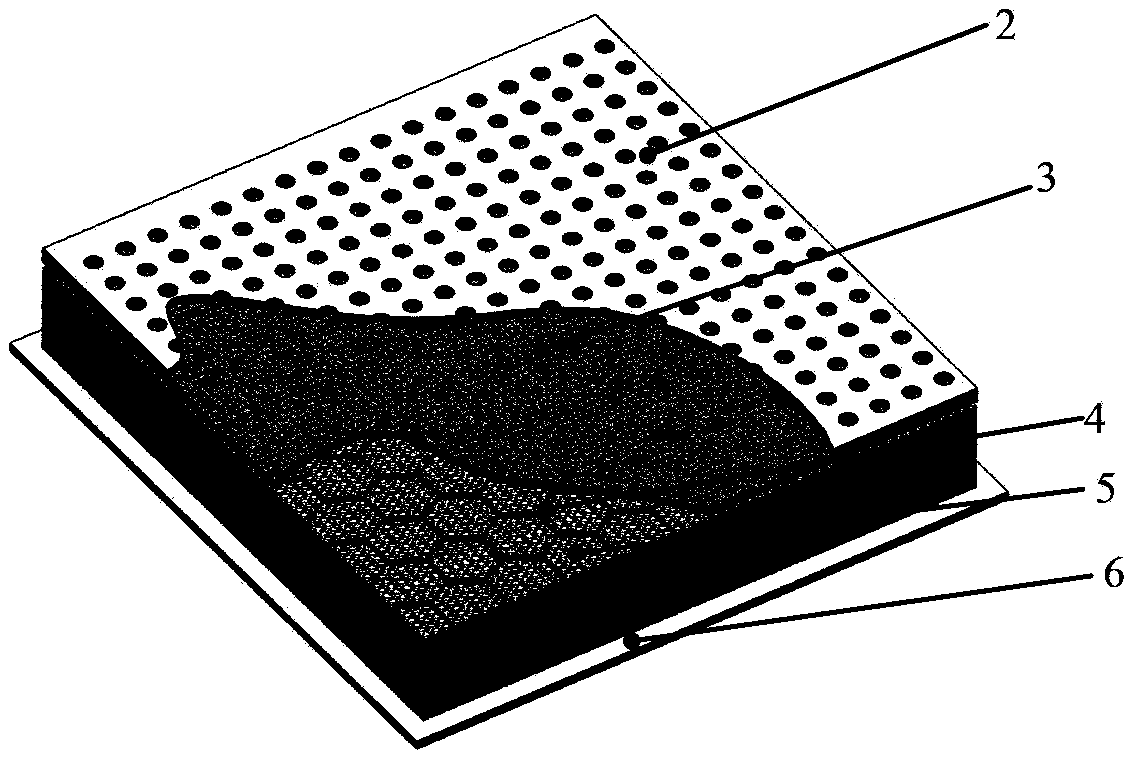
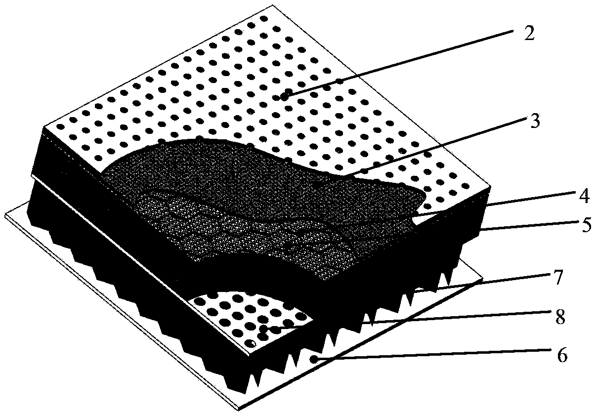
[0014] The invention provides a porous material acoustic lining which can be used for aero-engine noise reduction. The porous material is used as the inner core material of the aero-engine acoustic lining. The purpose is to use the porous material's excellent broadband sound absorption performance, high temperature resistance, and ultra-light The advantages of multi-function, combined with the perforated acoustic lining panel, constitute an excellent broadband sound-absorbing structure. In order to realize the above-mentioned acoustic lining structure, the present invention proposes the types of porous materials that can be applied to the interior of the aeroengine sound-absorbing acoustic lining, and provides several typical structural installation forms of the porous material acoustic lining.

[0015] figure 2 It ...


PUM


Abstract

The embodiment of the invention provides a broadband noise reduction porous-material acoustic liner. The acoustic liner comprises an acoustic liner panel, a honeycomb structure, a porous-material liner core and an acoustic liner bottom plate. The honeycomb structure is located between the acoustic liner panel and the acoustic liner bottom plate, and the porous-material liner core with a certain thickness is arranged in the honeycomb structure. According to the broadband noise reduction porous-material acoustic liner, the porous-material liner core is arranged in the honeycomb structure in a filling mode, therefore, structural mechanical properties can be satisfied, the acoustic liner can have an excellent broadband and stable noise elimination and reduction performance within a wide range of a high sound pressure level; the problems that porous materials in the acoustic liner are polluted and blocked by oil can be avoided by using an acoustically transparent layer undergoing oleophobic treatment; meanwhile, the porosity of the adopted porous materials is high, and therefore the acoustic liner can have the light feature. The acoustic liner can be applied to noise elimination and reduction of various types of equipment including aero-engines which have strength requirements and are located in severe environments.

Description

technical field [0001] The invention relates to the field of noise reduction, in particular to an aeroengine noise reduction sound lining structure. Background technique [0002] Aeroengines are one of the main noise sources of aircraft. In order to reduce the external radiated noise of aero-engines, sound-absorbing linings are often laid on the intake pipes and exhaust pipes of the engines, such as figure 1 . The traditional acoustic lining is a perforated plate honeycomb structure, that is, the honeycomb cells are fastened between the perforated panel and the rigid back plate to form multiple parallel Helmholtz resonators. This type of structure is characterized by good noise reduction performance at low and medium frequencies, but relatively poor at high frequencies. Since the noise spectrum in an aero-engine includes both a narrow-band spectrum (blade passing frequency and its multiplier) and a wide-band spectrum (flow noise caused by turbulence), mid- and high-freque...

Claims


Application Information

Patent Timeline
IPC IPC(8): G10K11/165
Inventor 王晓林彭锋
Owner INST OF ACOUSTICS CHINESE ACAD OF SCI
Learn More