
Nail gun

A nail gun and nail-shooting technology, applied in the field of nail guns, can solve problems such as the inability to maintain the temporary state of the work object, the inability to achieve a high degree of automation, and the reduction of product qualification rate, so as to achieve stable motion, easy control, and improve production efficiency Effect

Active Publication Date: 2014-07-02
河北简工科技有限公司
View PDF6 Cites 15 Cited by
  • Summary
  • Abstract
  • Description
  • Claims
  • Application Information

AI Technical Summary

Problems solved by technology

Intermittent addition of nails not only affects the continuity of production, cannot achieve a high degree of automation, and reduces production efficiency, but also may not maintain the temporary state of the work due to temporary shutdowns, such as the failure of the adhesive between the work, etc. , will result in unqualified products and reduce the qualified rate of products

Method used


Image

  • Nail gun
  • Nail gun

Examples


Embodiment Construction

[0028] Below in conjunction with accompanying drawing and embodiment the present invention is described in further detail:

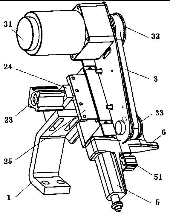
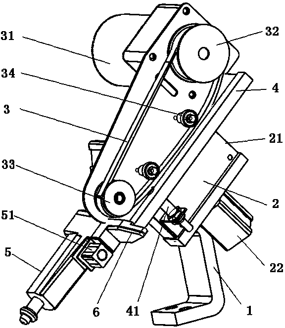
[0029] nail gun, such as Figure 1~2 As shown, it includes a machine base 1, a gun casing, a power part, a nail-shooting end, a nail-feeding part, and a control part. The machine base 1 is connected to the middle part of the nail-feeding part, and the nail-feeding part is connected to the nail-shooting end and the gun casing obliquely downward in turn, and the angle between the connecting line of the nail-feeding part, the nail-shooting end, and the gun shell and the horizontal plane is an acute angle.

[0030] In this embodiment, the machine base 1 is formed by bending a long steel plate, and is respectively arranged as a fixing seat, a support and a connecting end from bottom to top. A number of bolt holes are arranged on the fixing base, and the machine base 1 is fixed to the application equipment through bolts. The support is a section of folded pl...


PUM


Abstract

The invention discloses a nail gun which comprises a gun shell, a nailing end with a nail placement gap in the gun shell, a power part, a nail conveying part and a control part, wherein the nail conveying part comprises a nail bin for accommodating rows and stocks of straight nails, and a conveying mechanism, and a nail loading opening is formed in the sidewall of the nail bin; a jacking device for gradually jacking a single row of straight nails in the nail bin to a nail outlet in the top of the nail bin is arranged at the bottom of the nail bin; a lateral pushing device for laterally pushing the single row of straight nails at the nail outlet out of the nail bin is arranged on the upper part of the nail bin; the conveying mechanism comprises a conveying plate and a conveyor belt; the conveying plate is used for receiving the single row of straight nails pushed by the lateral pushing device; the conveyor belt is positioned above the conveying plate, and is matched and contacted with the conveying plate to load the single row of straight nails into the nail placement gap in the tail conveying end of the conveyor belt. The nail gun has the advantages of reasonable structure, stability in conveying, small size, convenience in operation and control and capability of continuously conveying the nails.

Description

technical field [0001] The invention relates to an industrial nail gun, in particular to a nail gun capable of realizing continuous feeding of large batches of nails. Background technique [0002] In many occasions in industrial production, it is necessary to use a nail gun to fasten products. The nail gun uses electricity or compressed air as the power to drive the nail rod instantly, so that the nail rod drives the nail (usually a straight nail, also called a nail) into the work. It is an essential tool for woodworking, building construction and other industries. [0003] In the prior art, the basic structure of a nail gun includes a gun housing, a power part, a nail end, a nail feeding part, and a control part. The power part is generally pneumatic, installed on the head of the nail gun, and its output end is connected to the nailing rod in the gun shell, which provides the driving force for the nailing rod to complete the action of hitting the nail, so that the nail is ...

Claims


Application Information

Patent Timeline
IPC IPC(8): B25C1/04
Inventor 白立辉崔浩白会彬高玉马亚涛白立强
Owner 河北简工科技有限公司
Learn More