Atomization plant for carbon removal liquid of automobiles

A technology for atomizing device and decarbonizing liquid, which is applied in the direction of liquid injection device and injection device, etc., can solve the problems of power drop, inability to work for a long time, and long time consumption.

Inactive Publication Date: 2014-06-25
宁波景虹环保科技有限公司
View PDF5 Cites 2 Cited by
  • Summary
  • Abstract
  • Description
  • Claims
  • Application Information

AI Technical Summary

Problems solved by technology

Therefore, the control of exhaust emissions is becoming more and more urgent, especially after automobiles or other walking machinery travel to a certain mileage, carbon deposits will be generated in the combustion chambers of gasoline engines or diesel engines, oxygen sensors, three-way catalytic converters and OBD systems If the sludge and carbon deposits in the above parts cannot be removed in time, the combustion performance of the engine will decrease, resulting in increased fuel consumption, reduced power, and excessive exhaust gas
The traditional way to solve the above problems is to add high calorific value hydrocarbons to the fuel of the automobile engine to burn carbon deposits or disassemble the engine for repair, or replace new parts. The disadvantages are high maintenance costs, long time consumption, and great damage to the engine.
[0003] And if the carbon removal liquid with better carbon removal effect can be atomized and then passed into the engine, then the misty carbon removal liquid can fully contact with the carbon deposit inside the engine and achieve a good removal effect. However, the current mist devices are bulky and complex in structure, and cannot work for a long time in high temperature or harsh environments, and cannot meet the decarbonization operation of automobile engines.

Method used


Image

  • Atomization plant for carbon removal liquid of automobiles
  • Atomization plant for carbon removal liquid of automobiles
  • Atomization plant for carbon removal liquid of automobiles

Examples


Embodiment Construction

[0024] Below in conjunction with specific embodiment, further illustrate the present invention. It should be understood that these examples are only used to illustrate the present invention and are not intended to limit the scope of the present invention. In addition, it should be understood that after reading the teachings of the present invention, those skilled in the art can make various changes or modifications to the present invention, and these equivalent forms also fall within the scope defined by the appended claims of the present application.

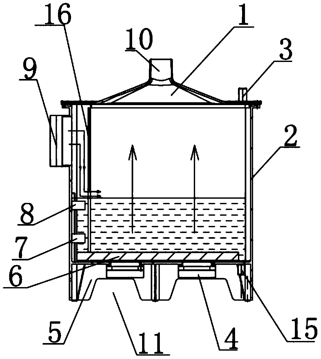
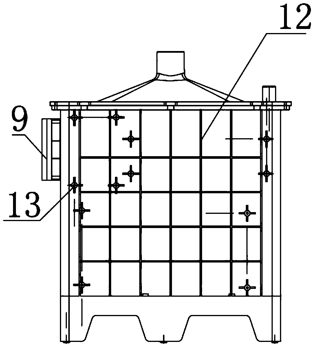
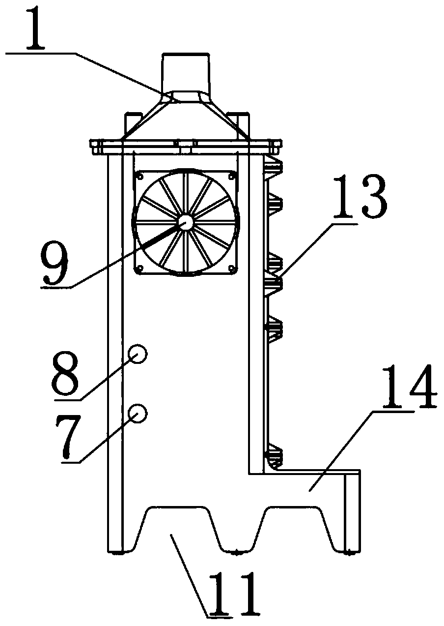
[0025] Such as figure 1 As shown in -4, the embodiment of the present invention relates to an atomization device for car carbon removal liquid, comprising an atomization box 2, a box upper cover 1 and a hollow base 5, the upper end surface of the atomization box 2 The upper cover 1 of the box body is installed, and the lower end of the atomization box body 2 is connected with a circle of hollow base 5 along the edge, and the ...


PUM


Abstract

The invention relates to an atomization plant for carbon removal liquid of automobiles. The atomization plant comprises an atomization tank, a tank upper cover and a hollow-out base. The tank upper cover is mounted on the upper end surface of the atomization tank, a circle of hollow-out base is connected to the lower end of the atomization tank along the edge of the atomization tank, an ultrasonic high-frequency vibrating plate is mounted on the lower end surface of the inside of the atomization tank in a clinging manner, ventilation holes are formed in a side wall of the atomization tank, an upper mist blowing fan is mounted on the side wall of the atomization tank, a carrying platform transversely extends out of a certain side of the hollow-out base, the certain side of the hollow-out base faces the atomization tank, two energy conversion holes are formed in the lower end surface of the atomization tank side by side, cooling fans are mounted at the lower end of the carrying platform and correspond to the energy conversion holes, and a main gas outlet hole is formed in the middle of the tank upper cover. The atomization plant has the advantages that the atomization plant is simple in operation and high in mist output, can work stably and is provided with cooling devices, a large quantity of carbon removal liquid can be atomized for a long term, and accordingly long-term carbon removal cleaning effects can be guaranteed for engines of the automobiles.

Description

technical field [0001] The invention relates to the field of automobile cleaning and environmental protection, in particular to an atomization device for automobile carbon removal liquid. Background technique [0002] With the rapid growth of the number of domestic automobiles, automobile exhaust emissions have become more and more polluting to the environment, and correspondingly severe smog has appeared across the country. Therefore, the control of exhaust emissions is becoming more and more urgent, especially after automobiles or other walking machinery travel to a certain mileage, carbon deposits will be generated in the combustion chambers of gasoline engines or diesel engines, oxygen sensors, three-way catalytic converters and OBD systems If the sludge and carbon deposits in the above parts cannot be removed in time, the combustion performance of the engine will be reduced, resulting in increased fuel consumption, reduced power, and excessive exhaust gas. The traditio...

Claims


Application Information

Patent Timeline
Patent Type & Authority Applications(China)
IPC IPC(8): B05B17/06
CPCB05B17/0615
Inventor 周岳泉杨晓东
Owner 宁波景虹环保科技有限公司
Why Eureka
Try Eureka