Standby power supply for electronic instrument equipment and control method of standby power supply

A technology of electronic equipment and backup power supply, which is applied in the direction of emergency power supply arrangements, electrical components, circuit devices, etc., can solve the problems of power supply control powerlessness, threats to the safety of electronic equipment, and limited application range, and achieve the effect of ingenious design

Active Publication Date: 2014-06-18
FOSHAN AIWEISI POWER SUPPLY CO LTD
View PDF5 Cites 1 Cited by
  • Summary
  • Abstract
  • Description
  • Claims
  • Application Information

AI Technical Summary

Problems solved by technology

[0004] There are two problems in the existing backup power supply control solutions for electronic instruments and equipment. On the one hand, most of the solutions cause the backup power supply to be always connected, and the storage, transportation, installation and commissioning stages before the final use of electronic instruments and equipment are always connected. They are all in a charged state, which not only affects the life of the backup power supply, but also threatens the safety of electronic instruments and equipment; The power supply control of some parts (such as LCD backlight, etc.) is powerless, and the application range is limited to a certain extent

Method used


Image

  • Standby power supply for electronic instrument equipment and control method of standby power supply
  • Standby power supply for electronic instrument equipment and control method of standby power supply
  • Standby power supply for electronic instrument equipment and control method of standby power supply

Examples


Embodiment 1

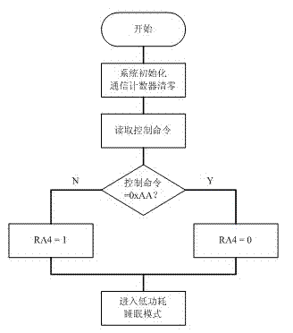
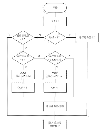
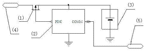
[0021] see figure 1 , a backup power supply for electronic equipment, the backup power supply includes a backup power output terminal, an electronic equipment auxiliary power input terminal 4, a semiconductor switching device is arranged between the backup power output terminal and the electronic equipment auxiliary power input terminal 4 1. The semiconductor switching device is also connected with a micro-power consumption controller, and the micro-power consumption microcontroller is powered by a backup power supply, and uses its communication interface to receive control commands from the main system of electronic equipment, and the micro-power consumption microcontroller Store the received control command in its on-chip non-volatile memory, and control the on or off of the semiconductor switching device according to the control command, so as to control the access or disconnection of the backup power supply.

Embodiment 2

[0023] see figure 1 , as an improvement of the present invention, the micro-power microcontroller is set to PIC12LF1822. In normal operation, the current of the chip is 8μA, and in sleep mode, the operating current is only 0.8μA, which further reduces power consumption. The rest of the structures and advantages are exactly the same as in Embodiment 1.

Embodiment 3

[0025] see figure 1 , as an improvement of the present invention, the semiconductor switching device is set as IRLML6402, its source is connected to the output terminal of the backup power supply, its drain is connected to the input terminal 4 of the auxiliary power supply of electronic equipment, and the gate is connected to the micro power consumption micro Controller 2 is connected to the control output pin. The rest of the structures and advantages are exactly the same as in Embodiment 1.


PUM


Abstract

The invention relates to a standby power supply for electronic instrument equipment. The standby power supply is characterized by comprising a standby power supply output end and an electronic instrument equipment assistant power supply input end; a semiconductor switch device is arranged between the standby power supply output end and the electronic instrument equipment assistant power supply input end; the semiconductor switch device is also connected with a micro-power consumption controller powered by the standby power supply; the micro-power consumption controller receives a control command of an electronic instrument equipment main system by a communication interface; the micro-power consumption controller stores the received control command into a nonvolatile memory on the chip of the micro-power consumption controller, and controls the on / off of the semiconductor switch device according to the control command, so the on / off of the standby power supply is controlled. According to the technical scheme, the service life of the standby equipment can be effectively prolonged and the safety of the electronic instrument equipment is ensured.

Description

technical field [0001] The invention relates to a backup power supply, in particular to a backup power supply for electronic equipment and a control method thereof, and belongs to the technical field of backup power supply control. Background technique [0002] The backup power supply is one of the essential components of many electronic instruments and equipment. Its function is that when the main power supply of the equipment fails, the backup power supply can protect the contents of the volatile memory, record possible failure data, prompt the type of failure, and maintain the equipment. The normal operation of some or even all systems. Backup power is usually implemented with a battery or a combination of a battery and a voltage regulator. [0003] Early backup and main power supplies were automatically switched between two low-cost diodes, but the voltage drop across the diodes reduced the voltage supplied to the device and shortened battery life. With the improvement...

Claims


Application Information

Patent Timeline
Patent Type & Authority Applications(China)
IPC IPC(8): H02J9/06
CPCY02B70/30Y04S20/20
Inventor 宫元九李阳杜立群
Owner FOSHAN AIWEISI POWER SUPPLY CO LTD
Why Eureka
Try Eureka