
Basin type insulator

A basin-type insulator and ring-shaped technology, applied in the field of electric power, can solve the problems of limited application occasions, large joint parts, complex structure, etc., and achieve the effect of strong flow capacity

Inactive Publication Date: 2014-06-18
POWERCHINA XIBEI ENG +3
View PDF6 Cites 3 Cited by
  • Summary
  • Abstract
  • Description
  • Claims
  • Application Information

AI Technical Summary

Problems solved by technology

This form of connection has a complex structure, a large joint, and requires a relatively large inner diameter of the busbar cylinder, which limits its application to a certain extent.

Method used


Image

  • Basin type insulator
  • Basin type insulator
  • Basin type insulator

Examples


Embodiment 1

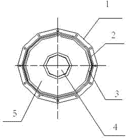
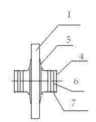
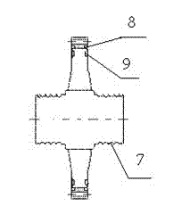
[0018] The pot insulator at least includes a cylindrical flange 1, a connecting conductor 4 and an insulating casting body 5; Left and right symmetrical with the annular insulating castable body 5 as the center; a cylindrical flange 1 is provided outside the annular insulating castable body 5; the upper and lower surfaces of the annular insulating castable body 5 near the outer circle are respectively provided with annular first grooves 8. The first O-ring 2 is provided in the first groove 8; the upper and lower surfaces of the cylindrical flange 1 near the inner circle are respectively provided with an annular second groove 9; the second groove 9 is provided with There is a second O-shaped sealing ring 3; three annular conductive grooves 7 are arranged at both ends of the connecting conductor 4, and each annular conductive groove 7 is covered with a spring contact 6.

Embodiment 2

[0020] Such as figure 1 , figure 2 with image 3 As shown, the pot insulator at least includes a cylindrical flange 1, a connecting conductor 4 and an insulating casting body 5; the insulating casting body 5 is ring-shaped, and a connecting conductor 4 is arranged in the hole of the annular insulating casting body 5. The connecting conductor 4 is left-right symmetrical with the annular insulating casting body 5 as the center; a cylindrical flange 1 is arranged outside the annular insulating casting body 5; the insulating casting body 5, the connecting conductor 4 and the cylindrical flange 1 form an integrated structure through casting. The upper and lower surfaces of the annular insulating casting body 5 near the outer circle are respectively provided with annular first grooves 8, and a first O-ring sealing ring 2 is arranged in the first groove 8; the cylindrical flange 1 is close to The upper and lower surfaces of the inner circle are respectively provided with a...


PUM


Abstract

The invention relates to a basin type insulator for high-current electric power transmission equipment. The basin type insulator at least comprises a tube type flange, a connecting conductor and an insulation casting body, and is characterized in that the insulation casting body is in an annular shape, the connecting conductor is arranged in a hole of the annular insulation casting body and is in bilateral symmetry by using the annular insulation casting body as the center, the tube type flange is arranged outside the annular insulation casting body, the upper and lower surfaces, near the excircle part, of the annular insulation casting body are respectively and correspondingly provided with first annular grooves, a first O-shaped sealing ring is arranged in each first groove, the upper and lower surfaces, near the inner circle part, of the tube type flange are respectively and correspondingly provided with second annular grooves, a second O-shaped sealing ring is arranged in each second groove, two ends of the connecting conductor are respectively provided with a plurality of annular conducting grooves, and a spring contact is sheathed on each annular conducting groove. The basin type insulator has the advantages that the problem of usage occasion limitation of the traditional basin type insulator is solved, and in addition, the sealing performance is good.

Description

technical field [0001] The invention particularly relates to a basin-type insulator used for large-current power transmission equipment, which belongs to the field of electric power. Background technique [0002] In ordinary pot insulators, the connection between the pot insulator and the internal conductor of the GIB is a plug-in type, that is, the connection part of the pot insulator is designed as a plug, and the connection part of the conductor is designed as a socket. The combination of the two forms a current channel to transmit power. . This form of connection has a complex structure, a large joint, and requires a relatively large inner diameter of the busbar cylinder, which limits its application to a certain extent. GIB is the abbreviation of "Gas insulated transmission bus", and the Chinese name is "gas insulated transmission bus". Contents of the invention [0003] The invention proposes a new type of basin-type insulator to improve the problem of limited appl...

Claims


Application Information

Patent Timeline
IPC IPC(8): H01B17/30H01B17/40
Inventor 阮全荣万青康本贤谢小平邹斌桑志强杨镇澴李学斌王亚红杨存龙庞秀兰
Owner POWERCHINA XIBEI ENG
Learn More