Adjusting structure of lamp irradiating angles

A technology for irradiating angles and adjusting structures, which is applied to the components of lighting devices, lighting devices, lighting auxiliary devices, etc., can solve the problems of reducing work efficiency, unfavorable product safety use, and long time, so as to improve the safety of use and design The effect of low processing cost and improved work efficiency

Active Publication Date: 2014-06-11
OCEANKING DONGGUAN LIGHTING TECH +2
View PDF5 Cites 6 Cited by
  • Summary
  • Abstract
  • Description
  • Claims
  • Application Information

AI Technical Summary

Problems solved by technology

[0004] However, in actual situations, the following two situations are often encountered: one is when there is no tool and the angle of illumination of the lamp cannot be directly adjusted manually, and the other is when the installation position of the lamp is relatively high. Angle adjustment is not easy to achieve. On the one hand, it will take a lot of time to find tools or try to climb to the same height as the lamp, which greatly reduces work efficiency; The phenomenon of not being able to adjust the tool or using the site conditions to climb to the same height as the lamp, so that the irradiation angle of the lamp cannot be adjusted, thereby greatly reducing the irradiation effect of the lamp; at the same time, climbing up to adjust the irradiation of the lamp At an angle, the staff may fall and be injured, which is not conducive to the safe use of the product

Method used


Image

  • Adjusting structure of lamp irradiating angles
  • Adjusting structure of lamp irradiating angles
  • Adjusting structure of lamp irradiating angles

Examples


Embodiment Construction

[0024] In order to make the object, technical solution and advantages of the present invention clearer, the present invention will be further described in detail below in conjunction with the accompanying drawings and embodiments. It should be understood that the specific embodiments described here are only used to explain the present invention, not to limit the present invention.

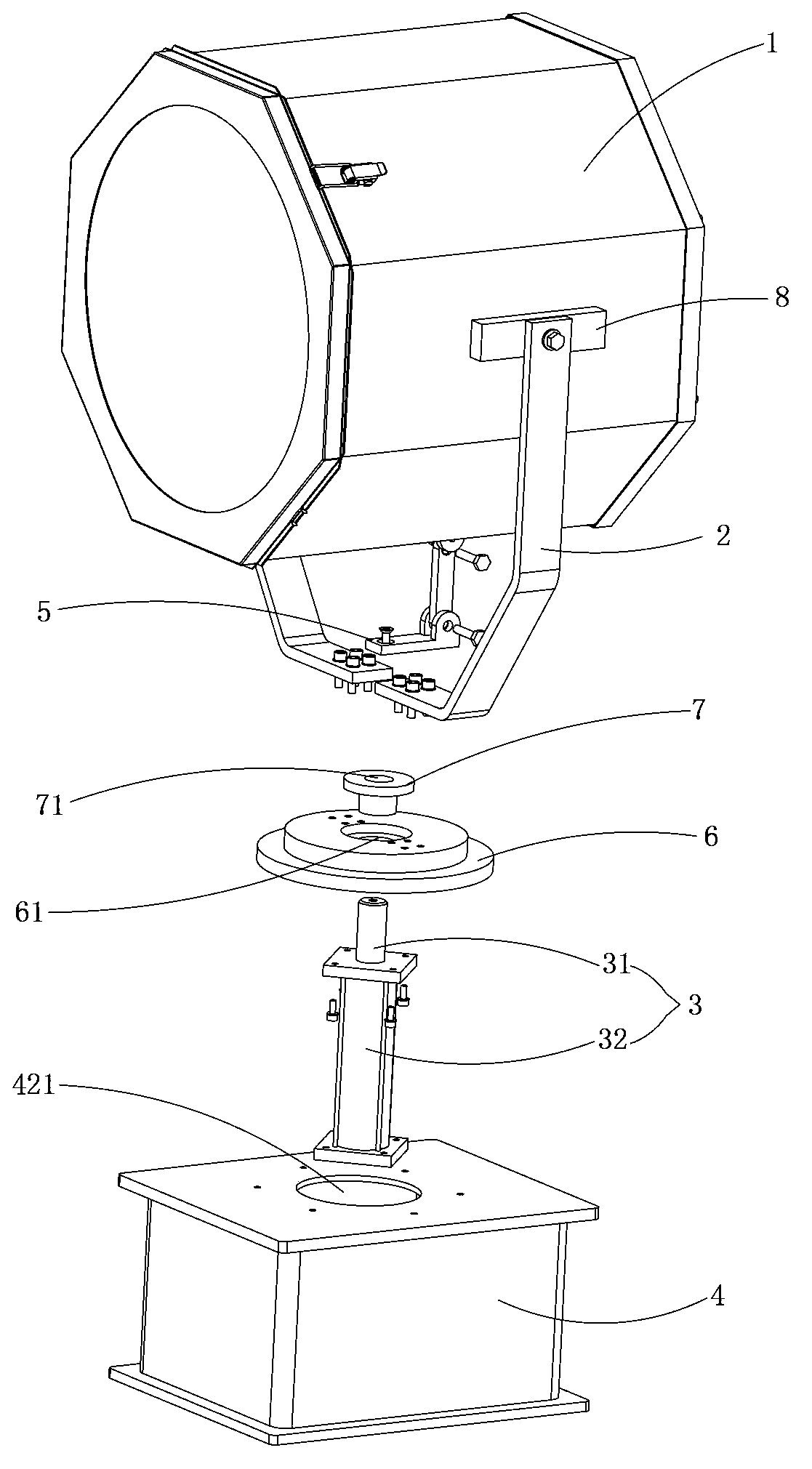
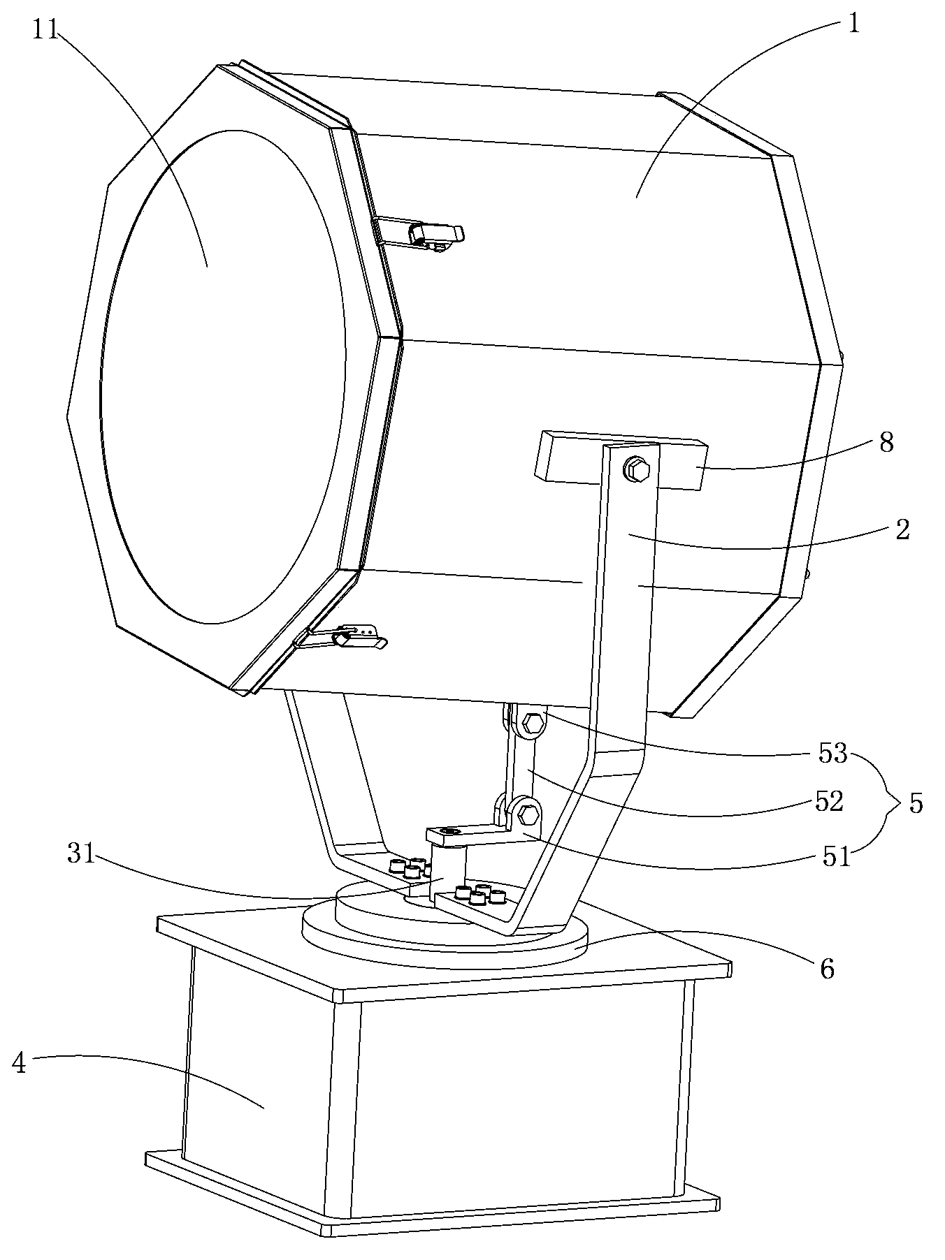
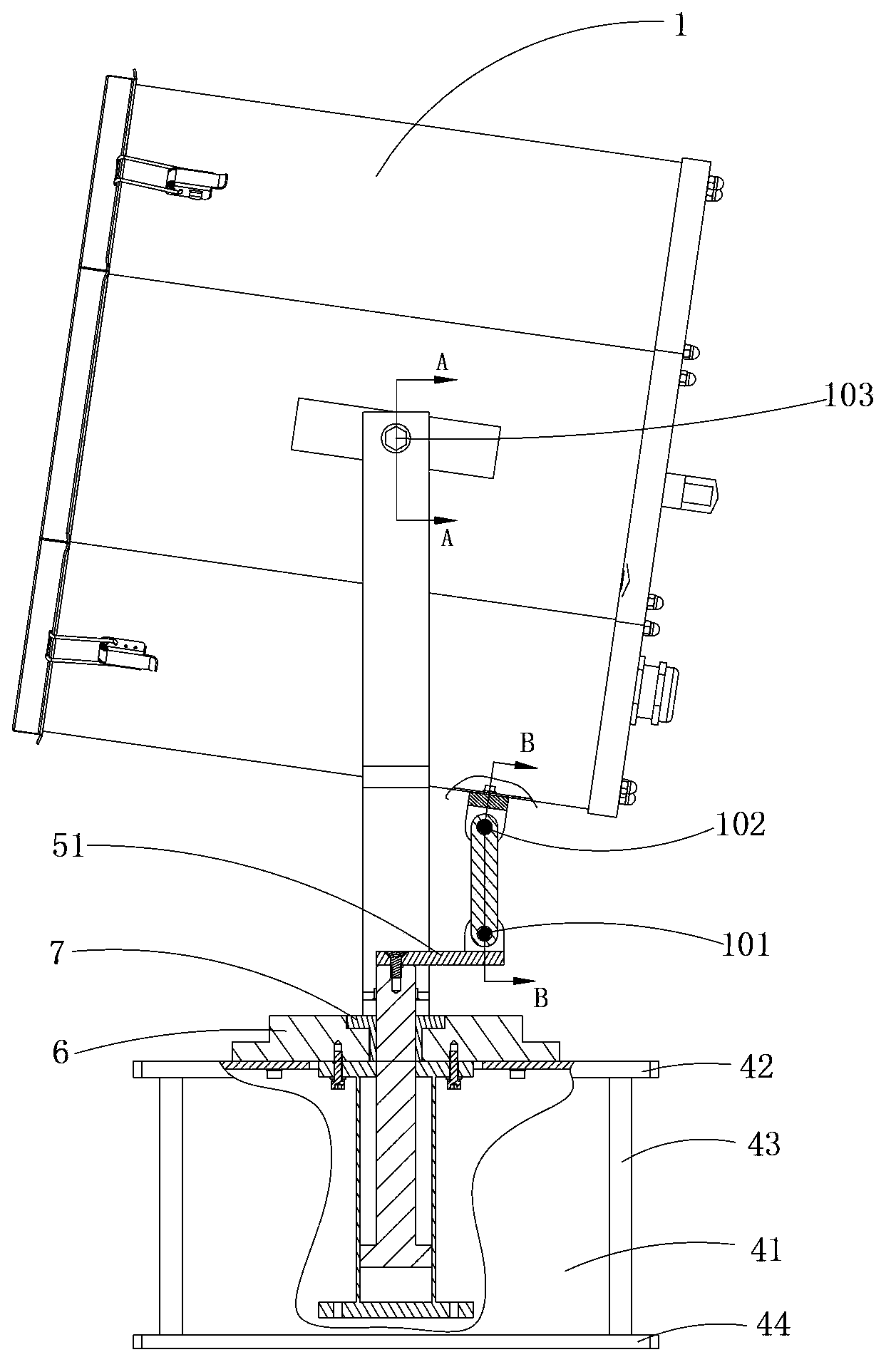
[0025] Such as Figure 1 ~ Figure 3 As shown, the structure for adjusting the illumination angle of the lamp provided by the embodiment of the present invention includes a lamp body 1, a fixing seat 4 having an inner cavity 41, a bracket 2 for fixing the lamp body 1 on the fixing seat 4, A connecting rod assembly 5 for driving the lamp body 1 to swing and a push rod assembly 3 for driving the connecting rod assembly 5 to move, one end of the bracket 2 is fixedly connected to the lamp body 1, and the other end is fixedly connected to the The fixed seat 4; the push rod assembly 3 is located in the i...


PUM


Abstract

The invention is applicable to the technical field of lamp mounting and discloses an adjusting structure of lamp irradiating angles. The adjusting structure comprises a lamp body, a fixing seat with an inner cavity and a support for fixing the lamp body on the fixing seat. One end of the support is fixedly connected with the lamp body, and the other end thereof is fixedly connected with the fixing seat. The adjusting structure further comprises a connecting rod component for driving the lamp body to swing and a push rod component for driving the connecting rod component to move. The push rod component is disposed in the inner cavity of the fixing seat and provided with a push rod extending out of the inner cavity. One end of the connecting rod component is fixedly connected with the push rod, and the other end thereof is fixedly connected with the lamp body. Due to the fact that the push rod component is fixed on the fixing seat, a worker can easily control the action of the adjusting device manually or electrically on the ground, no extra tools are needed, climbing is avoided effectively, work efficiency is increased greatly, and product application safety is increased. In addition, the adjusting structure is simple and compact in structure and simple to operate.

Description

technical field [0001] The invention belongs to the technical field of lamp installation, and in particular relates to a structure for adjusting the irradiation angle of a lamp. Background technique [0002] In the prior art, the installation structure of a lamp generally includes a lamp body, a bracket and a fixing seat. One end of the bracket is connected to the lamp body, and the other end is connected to the fixing seat. In this way, the lamp body is effectively fixed on the fixing seat through the bracket. [0003] In specific applications, in order to make the illumination effect of the lamp better, the illumination angle of the lamp is often adjusted according to specific conditions. In the prior art, when adjusting the irradiation angle of the lamp, it is generally necessary to use a tool (screwdriver or wrench) or directly loosen the connection between the lamp body and the bracket by hand, and then change the distance between the lamp body and the bracket by rotati...

Claims


Application Information

Patent Timeline
Patent Type & Authority Applications(China)
IPC IPC(8): F21V21/15
Inventor 周明杰彭冬来
Owner OCEANKING DONGGUAN LIGHTING TECH
Why Eureka
Try Eureka