
Torsion bar for seat belt retractor, seat belt retractor and seat belt assembly

A technology of seat belt retractor and torsion bar, applied in the field of seat belts, can solve the problem of not providing seat belt modification, etc., and achieve the effect of protecting users

Active Publication Date: 2016-06-29
和励科技有限公司
View PDF6 Cites 0 Cited by
  • Summary
  • Abstract
  • Description
  • Claims
  • Application Information

AI Technical Summary

Problems solved by technology

In the prior art, there is no technical inspiration for transforming the safety belt of the aforementioned prior art into a progressive force-limiting safety device

Method used


Image

  • Torsion bar for seat belt retractor, seat belt retractor and seat belt assembly
  • Torsion bar for seat belt retractor, seat belt retractor and seat belt assembly
  • Torsion bar for seat belt retractor, seat belt retractor and seat belt assembly

Examples


no. 1 example

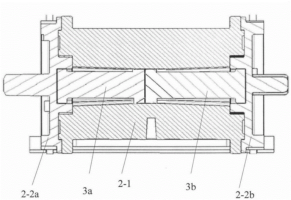
[0051] In this embodiment, the torsion bar is rod-shaped, and the torsion bar is divided into two sections in the axial direction. Both ends of each segment are provided with circumferential external teeth, please refer to Figure 5 , which is a structural schematic diagram of a section of the first embodiment of the torsion bar of the present invention, and the two ends of the torsion bar section 3a are provided with external teeth 3-2a and external teeth 3-2b. When the two sections of torsion rods are integrated, the two ends of the two sections of torsion rods are butted together, the end surfaces are in contact with each other, and the outer teeth of the opposite ends are aligned with each other to form an integral torsion rod. The outer teeth located at the two outer ends of the torsion bar match with the inner teeth of the central concave holes on the end faces of the two end caps of the retractor (the matching relationship between the torsion bar and the retractor is de...

no. 2 example

[0079] Please refer to Figure 12 , which is a schematic diagram of the second embodiment of the torsion bar of the present invention. In this embodiment, the torsion bar is an integral type, and circumferential external teeth (external teeth 3-2, external teeth 303 and external teeth 3-1) are also arranged at both ends and the middle of the torsion bar, wherein the torsion bar is located in the middle of the torsion bar. The effective lengths of the rod segments 3a and 3b on both sides of the circumferential external teeth 3-1 are different in the axial direction. Other aspects of the structure of the torsion bar in this embodiment and the assembly and cooperation relationship with the seat belt retractor are the same as those of the first embodiment above, and have the same technical effect as the torsion bar of the first embodiment above, here No longer.

[0080] In addition, the axial length of the torsion bar of the present invention can also be greater than the axial l...


PUM


Abstract

The invention provides a torsion bar used for a safety belt retractor. The torsion bar is bar-shaped, and circumferential outer teeth are arranged at two ends and in the middle of the torsion bar. The effective lengths and the diameters of bar sections on two sides of the circumferential outer teeth in the middle of the torsion bar are different. In a preferable scheme, the torsion bar is divided into two sections connected in a butting mode in the axial direction, circumferential teeth are arranged at two ends of each torsion bar section, the tooth shapes of the outer teeth at the abutting connection ends of the two torsion bar sections are aligned, and the circumferential outer teeth at the abutting connection ends of the two torsion bar sections form the peripheral outer teeth arranged in the middle. The torsion bar is a decrease force limit type torsion bar and can achieve two-stage decrease force limit when applied to an installation belt. A safety belt retractor using the torsion bar and a safety belt assembly using the safety belt retractor are further provided.

Description

technical field [0001] The invention relates to safety belt technology, in particular to a torsion bar for a safety belt retractor. The present invention also relates to a seat belt retractor using the torsion bar, and a seat belt assembly using the above seat belt retractor. Background technique [0002] Seat belts are important passive safety components used in automobiles. When the vehicle collides, the seat belt can protect the user from or reduce secondary injuries during the collision. [0003] The standard three-point safety belt originally designed to be applied to a car seat only includes a locking mechanism and a webbing for fixing the user (human body). When the vehicle collides, the locking mechanism is locked, and the webbing is no longer stretched outward, thereby binding the user to the car seat. [0004] However, due to the rapid change of speed at the moment of collision, the momentum change time caused by the speed change during collision is very short, ...

Claims


Application Information

Patent Timeline
Patent Type & Authority Patents(China)
IPC IPC(8): B60R22/34
Inventor 刘学军
Owner 和励科技有限公司
Learn More