Interrupt switch structure of SIM card
A technology of switch structure and conductive pins, which is applied to the parts of the connection device, contact parts, electrical components, etc., can solve the problems of high production cost, complex interrupt switch structure, and easy failure of shrapnel, so as to save internal space, light and thin Optimized design and guaranteed reliability
- Summary
- Abstract
- Description
- Claims
- Application Information
AI Technical Summary
Problems solved by technology
Method used
Image
Examples
Embodiment 1
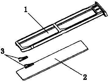
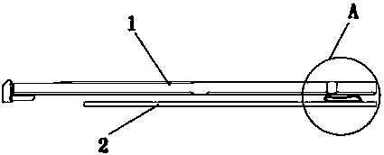
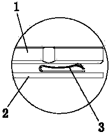
[0024] like figure 1 , figure 2 and image 3 As shown, an interrupt switch structure for a SIM card includes a SIM card holder 1 and conductive pins arranged in pairs. A pair of interrupting pin shrapnel 3 is provided, and the pair of interrupting pin shrapnel 3 is welded on the mobile phone main board 2, one interrupting pin shrapnel 3 is connected with the interrupt signal circuit, and the other interrupt pin shrapnel 3 is connected with the ground signal circuit. The back side of the SIM card tray 1 is provided with a conductive layer, and when the SIM card tray 1 is inserted into the working position, the two interrupting pin springs 3 respectively abut against both sides of the back side of the SIM card tray 1 .
[0025] like Figure 7 As shown, the interrupting leg elastic piece 3 is provided with a protrusion 31 , and the protrusion 31 is located on the side of the interrupting leg elastic piece 3 that abuts against the back of the SIM card tray 1 . The welding sur...
Embodiment 2
[0028] like Figure 4 , Figure 5 and Image 6 As shown, a kind of interruption switch structure of SIM card, comprises SIM card holder 1, also comprises the conductive pin that is arranged in pairs, and conductive pin is the interrupt pin shrapnel 3, and the interrupt pin shrapnel 3 that adopts in the present embodiment and embodiment One of the same. There are two pairs of interrupting pin shrapnel 3, and the two pairs of interrupting pin shrapnel 3 are all welded on the mobile phone motherboard 2. The back side of the SIM card tray 1 is provided with a conductive layer. The foot springs 3 respectively abut against both sides of the back of the SIM card, the two interrupting foot springs 3 on one side are connected to the interruption signal circuit, and the two interruption foot springs 3 on the other side are connected to the ground signal circuit.
[0029] When in use, put the SIM card into the SIM card tray 1, insert the SIM card tray 1 into the mobile phone, and when...
PUM
 Abstract
Description
Claims
Application Information
 - R&D
- Intellectual Property
- Life Sciences
- Materials
- Tech Scout
- Unparalleled Data Quality
- Higher Quality Content
- 60% Fewer Hallucinations
Browse by: Latest US Patents, China's latest patents, Technical Efficacy Thesaurus, Application Domain, Technology Topic, Popular Technical Reports.
© 2025 PatSnap. All rights reserved.Legal|Privacy policy|Modern Slavery Act Transparency Statement|Sitemap|About US| Contact US: help@patsnap.com


