Maglev Train Bogie with Elevating Support Slider

A technology for magnetic levitation trains and bogies, which is applied to bogies, railway car body parts, transportation and packaging, etc., can solve the problems of damage to the traction motor 7, affecting the performance of the suspension system, and reducing the traction efficiency of the traction motor 7, so as to achieve high safety. reliability and reliability, the effect of guaranteed performance

Active Publication Date: 2016-12-07
NAT UNIV OF DEFENSE TECH
View PDF7 Cites 0 Cited by
  • Summary
  • Abstract
  • Description
  • Claims
  • Application Information

AI Technical Summary

Problems solved by technology

[0004] like figure 2 and image 3 As shown, the position of the existing support slider 8 relative to the box girder 4 is fixed. When the train is alighted, the support slider 8 is the landing point and support point of the train. Due to the elastic deformation of the anti-roll beam group 3, according to Moment balance conditions and the geometric constraints of the bogie, the bogie module 2 will roll outward with the support slider 8 as the fulcrum, the outer gap between the traction motor 7 and the track 9 will be smaller than the gap between the traction motor 7 and the inner side of the track 9, if the support slider The thickness of the block 8 is set to be small, and the outside of the traction motor 7 may touch the rail 9 when getting off the car, resulting in damage to the traction motor 7
For the above problems, there are two solutions in the prior art: one is to increase the thickness of the supporting slider 8, which causes the initial suspension gap of the electromagnet 6 to decrease, that is, the gap between the supporting slider 8 and the track 9 after the train is suspended. The gap is reduced, and the support slider 8 is easy to touch the track 9 during the operation of the train, which affects the performance of the suspension system; the second is to improve the installation position of the traction motor 7, but this solution will reduce the traction efficiency of the traction motor 7

Method used


Image

  • Maglev Train Bogie with Elevating Support Slider
  • Maglev Train Bogie with Elevating Support Slider
  • Maglev Train Bogie with Elevating Support Slider

Examples


Embodiment Construction

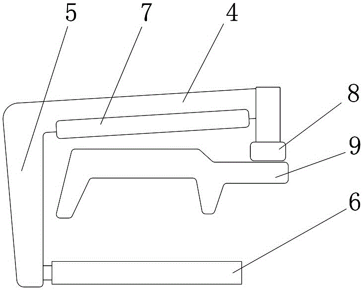
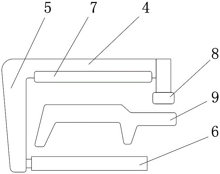
[0027] Figure 4 to Figure 7 It shows the first embodiment of the magnetic levitation train bogie with lifting support slider of the present invention, the magnetic levitation train bogie with lift support slider includes anti-roll beam group 3 and a pair of bogie modules 2, a pair of The bogie module 2 is connected through the anti-roll beam group 3. The bogie module 2 includes a box girder 4 and a support slider 8 for alighting and emergency braking. The support slider 8 is installed inside the box girder 4, and the support slider 8 An adjustment device 1 for adjusting the lifting of the support slider 8 is provided between the box beam 4. In this embodiment, the bogie module 2 also includes a support arm 5, an electromagnet 6 and a traction motor 7. The support arm 5 and the box girder 4 connection, the electromagnet 6 is installed on the support arm 5, the traction motor 7 is hung on the box girder 4, and the adjustment device 1 for adjusting the lifting of the support sli...


PUM


Abstract

The invention discloses a magnetically levitated train steering frame with lifting supporting sliding blocks. The magnetically levitated train steering frame comprises an anti-rolling beam group and a pair of steering frame modules. The pair of steering frame modules is connected through the anti-rolling beam group. The steering frame modules comprise beam boxes and the supporting sliding blocks for training falling and emergency braking. The supporting sliding blocks are arranged on the inner sides of the beam boxes. Adjusting devices for adjusting supporting sliding block lifting are arranged between the supporting sliding blocks and the beam boxes. The magnetically levitated train steering frame with the lifting supporting sliding blocks has the advantages of being simple in structure, safe and reliable, a dragging motor can be protected from damage, and dragging efficiency can be guaranteed.

Description

technical field [0001] The invention relates to a magnetic levitation train, in particular to a magnetic levitation train bogie with an elevating support slider. Background technique [0002] Electromagnetic Suspension (EMS for short) low-speed maglev train is a new type of vehicle that relies on the attraction between the electromagnet installed on the train and the track to make the train float on the track. It has a small turning radius, Strong climbing ability, no noise pollution and other advantages. [0003] At present, EMS low-speed maglev trains usually use modular bogies, such as figure 1 As shown, each bogie is composed of a pair of bogie modules 2 connected by anti-roll beam groups 3, and the bogie modules 2 include box girders 4, bracket arms 5, electromagnets 6, traction motors 7 and support sliders 8, The electromagnet 6 is installed on the support arm 5 and placed under the track 9 to generate electromagnetic levitation force. The traction motor 7 is hoisted...

Claims


Application Information

Patent Timeline
Patent Type & Authority Patents(China)
IPC IPC(8): B61F5/50B61F5/00
Inventor 李杰张锟周丹峰李冠醇刘耀宗
Owner NAT UNIV OF DEFENSE TECH
Why Eureka
Try Eureka