
Economical recharge system for sandstone geothermal tail water

A technology of geothermal tail water and geothermal water, applied in geothermal energy power generation, heating devices, filtration circuits, etc., can solve the problems of reduced filtering effect, large installation span, and difficult cleaning, etc., to remove accumulated blockages and reduce workload , The effect of easy installation and operation

Active Publication Date: 2014-05-28
CHINA PETROCHEMICAL CORP +2
View PDF6 Cites 11 Cited by
  • Summary
  • Abstract
  • Description
  • Claims
  • Application Information

AI Technical Summary

Problems solved by technology

On the whole, the currently used recharge devices mainly have the following characteristics: (1) They are all two-stage filtration, and the precision setting span of the front and back stages is too large. Such facilities are likely to cause excessive workload of the filter during operation; on the other hand, despite the filtration, after a long period of recharge, the recharge well will also be clogged to varying degrees, resulting in reduced recharge efficiency
(2) The recharging device failed to consider the design of the entire system from mining to recharging, resulting in mutual interference in the hydraulic conditions of the pipeline
(3) During the use of the quartz sand tank filter device, geothermal water with high salinity and complex composition is likely to cause agglomeration, which will reduce the filtering effect and is not easy to clean
The nitrogen protection device and the quartz sand tank occupy too large an area, so it is not easy to promote and use it on a large scale

Method used


Image

  • Economical recharge system for sandstone geothermal tail water

Examples


Embodiment Construction

[0027] In order to make the technical means, creative features, goals and effects achieved by the present invention easy to understand, the present invention will be further described below in conjunction with specific illustrations.

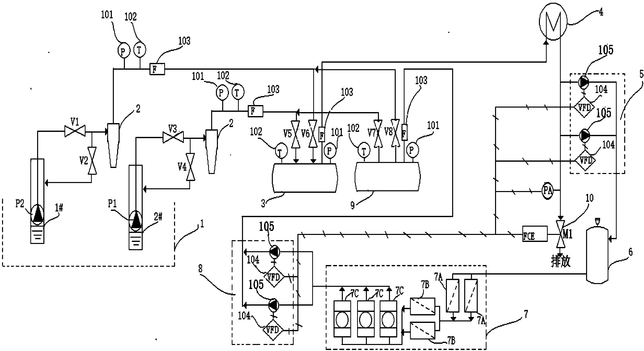
[0028] as attached figure 1 The technical problem to be solved by the present invention is to provide a sandstone geothermal tail water economic recharge system, which includes:

[0029] At least one set of geothermal wells (1), geothermal water desanding device (2), manifold (collector) (3, 9), heat exchange device (4), frequency conversion pressurization device (5, 8), degassing device (6), tail water filter device (7) and electric regulating valve (10);

[0030] Wherein, the geothermal well (1) is connected to the geothermal water desanding device (2), and the geothermal water desandering device (2) is connected to the The above-mentioned heat exchange device (4) is connected, and the heat exchange device (4) is respectively connected with ...


PUM


Abstract

The invention relates to a geothermal tail water recharge technology in geothermal exploitation and utilization process. Besides a geothermal well, the overall system mainly adopts geothermal water desanding devices, sub-catchments, a heat exchange device, frequency conversion pressurizing devices, a degassing device, a tail water filter and an electric control valve. Through the adjustment of the system, functions of the exploitation and the recharge of the geothermal well are converted, cumulative blockade caused by long term recharge of a simple opening geothermal well is eliminated, and the chronicity of the recharge is ensured; through the adoption of a standby filter, the sustainability and the continuity of the recharge process are ensured; three-level filters with different precisions are coordinated and adopted, besides, PID control with an automatic regulatory function and enabling the overall system to realize automatic frequency rising and lowering of pressure pumps and opening degree of the electric control valve is designed, and mutual interference between exploitation and recharge of the geothermal well is eliminated. The system is suitable for sandstone stratums in various areas, through the adoption of the system, economical and effective recharge can be conducted on tail water after the geothermal comprehensive utilization, and sustainable development of geothermal exploitation and utilization can be ensured.

Description

technical field [0001] The invention belongs to the field of geothermal development and utilization, and in particular relates to sandstone geothermal tail water recharge. technical background [0002] As a renewable energy source, geothermal resources have been included in the "Twelfth Five-Year Plan" energy plan. How to make good use of geothermal resources is one of the ideal choices for energy saving and emission reduction. [0003] Geothermal water is mined from the formation to the ground for heat exchange and utilization. The temperature, pressure and other working conditions of the geothermal water change, and the composition of the geothermal water changes after contact with the air. Blockages of different origins were formed, resulting in a decrease in the recharge flow rate of the geothermal tail water in the sandstone thermal storage, a decrease in the recharge efficiency, and even failure to recharge. [0004] The existing refilling device basically consists o...

Claims


Application Information

Patent Timeline
IPC IPC(8): B01D36/02B01D36/00F24J3/08
CPCY02E10/10
Inventor 刘世良杨荣亮郭世炎韩惠奇
Owner CHINA PETROCHEMICAL CORP
Learn More