
Articulated canted wingtips

A sloping, wingtip technology that is used in wing adjustment, affecting air flow across the surface of the aircraft, drag reduction, etc., and can solve problems such as increasing fuel costs, operating costs, and increasing aircraft weight.

Active Publication Date: 2020-02-11
THE BOEING CO
View PDF6 Cites 2 Cited by
  • Summary
  • Abstract
  • Description
  • Claims
  • Application Information

AI Technical Summary

Problems solved by technology

However, these size increases increase aircraft weight, which is undesirable because of increased operating costs such as fuel costs

Method used


Image

  • Articulated canted wingtips
  • Articulated canted wingtips
  • Articulated canted wingtips

Examples


Embodiment Construction

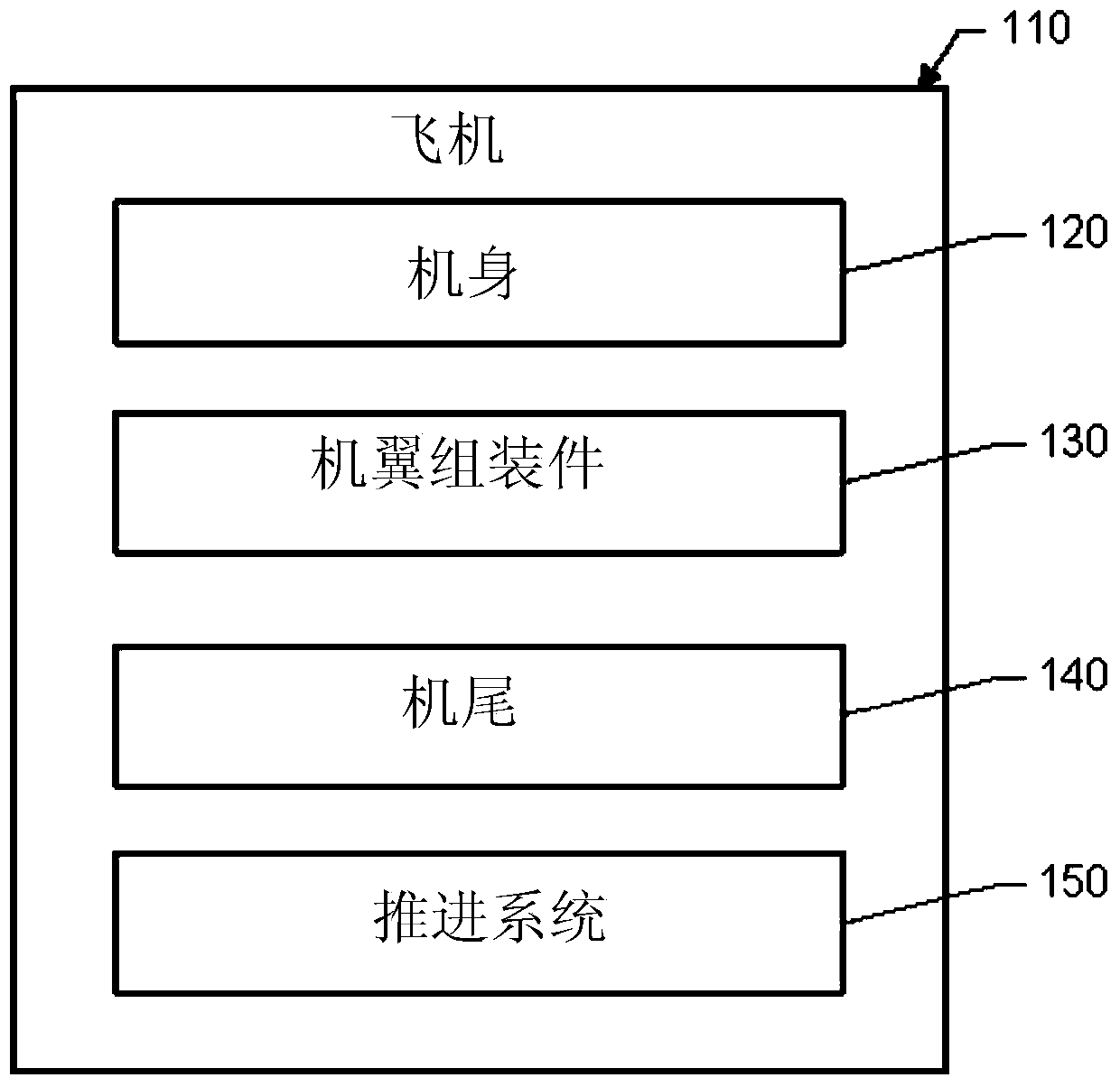
[0026] refer to figure 1 , shows an aircraft 110 including a fuselage 120 , a wing assembly 130 attached to the fuselage 120 , and a tail 140 attached to the fuselage 120 . One or more propulsion units 150 are coupled to fuselage 120 , wing assemblies 130 , or other portions of aircraft 110 . Each wing assembly 130 includes a main wing and a wing tip that are hinged together for movement between a folded position and an extended position. The main wings can be swept forward, have zero sweep, or be swept backward. The wingtips are foldable to accommodate the aircraft 110 in the runway, taxiway, and gate areas. Folding the wingtips enables the aircraft to comply with airport codes, such as ICAO codes. The wingtips are extendable before take-off to increase the wingspan. The high wingspan ensures high aerodynamic efficiency.

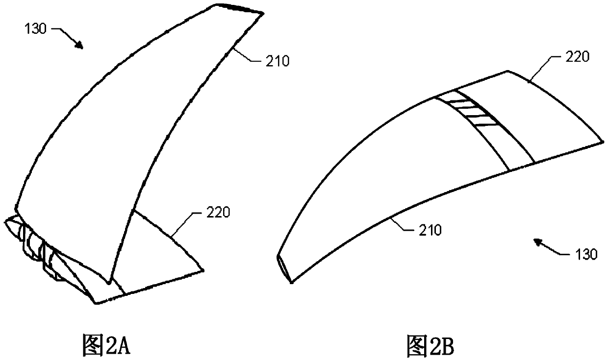
[0027] Figure 2A and 2B is an illustration of wing assembly 130 including raked wingtip 210 hinged to main wing 220 . Figure 2A showing the wingt...


PUM


Abstract

The present invention relates to articulated raked wingtips. The wing assembly includes a raked wingtip having an outboard portion hinged to a main wing having at least one movable control surface, and a raked wingtip inboard portion. The outboard portion of the raked wingtip does not carry any movable flight control surfaces.

Description

technical field [0001] Long span wings are desirable for commercial aircraft because they are more aerodynamically efficient than short wings. The greater the aerodynamic efficiency, the lower the fuel consumption, which reduces operating costs. Background technique [0002] However, the current airport design location limits the aircraft wingspan. Airport designs are based on International Civil Aviation Organization (ICAO) codes A to F, which establish dimensional limitations for wingspan, landing gear width, length, etc. For example, ICAO Code E airports limit wingspans to less than 65 meters so that aircraft can fit on runways, taxiways, and gate areas. [0003] Folding wing designs can be used to reduce the span of these wings to accommodate existing airport infrastructure constraints. Folding wings can be folded to accommodate runways, taxiways, and gate areas, and they can be extended prior to takeoff to increase wingspan. [0004] Folding wing designs are commonl...

Claims


Application Information

Patent Timeline
Patent Type & Authority Patents(China)
IPC IPC(8): B64C3/56
CPCB64C3/56B64C23/072Y02T50/10B64C3/58
Inventor P·W·德斯M·S·古德S·萨库拉伊J·A·柯德S·J·福克斯M·A·拉森B·R·福克斯S·P·沃克G·M·圣蒂尼
Owner THE BOEING CO
Learn More