Vehicle drive-control device
A driving control and vehicle technology, applied to vehicle components, vehicle safety arrangements, automatic steering control components, etc., can solve problems such as uneasiness and discomfort
- Summary
- Abstract
- Description
- Claims
- Application Information
AI Technical Summary
Problems solved by technology
Method used
Image
Examples
no. 1 approach
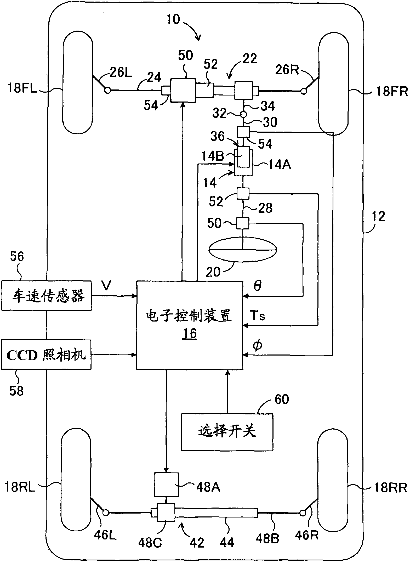
[0085] figure 1 It is a schematic configuration diagram showing the first embodiment of the vehicle travel control device according to the present invention applied to a vehicle equipped with an electric power steering device and a rear-wheel steering device.
[0086] in figure 1 Here, the travel control device 10 according to the present invention is installed in a vehicle 12 and includes a steering angle variable device 14 and an electronic control device 16 that controls the steering angle variable device 14. In addition, in figure 1 Here, reference numerals 18FL and 18FR respectively denote the left and right front wheels as steering wheels of the vehicle 12, and reference numerals 18RL and 18RR respectively denote the left and right rear wheels. Using the rack-and-pinion type electric power steering device 22 that is driven in response to the operation of the steering wheel 20 by the driver, the left and right front wheels, which are steered wheels, are turned by the rack 24 ...
no. 2 approach
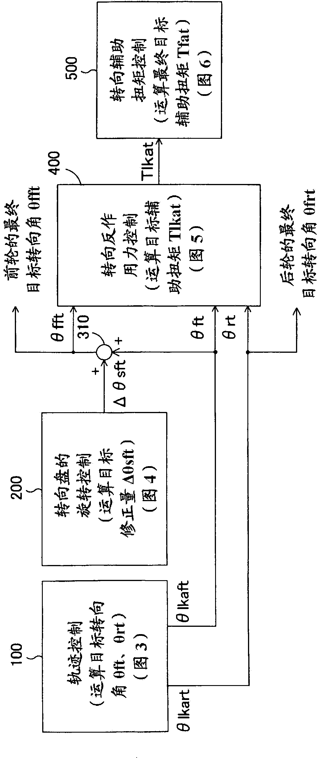
[0150] Figure 17 It is a block diagram showing the overall travel control of the vehicle in the second embodiment of the vehicle travel control device according to the present invention. In addition, in Figure 17 Middle, right and figure 2 The module label corresponding to the module shown is figure 2 The reference numerals marked in the same reference numerals.
[0151] In the second embodiment, in addition to the trajectory control module 100, the steering wheel rotation control module 200, the steering reaction force control module 400, and the steering reaction force control module 500, a vehicle yaw angle control module 600 is also provided. In addition, the control in each module other than the yaw angle control module 600 is the same as in the case of the above-mentioned first embodiment.
[0152] The yaw angle control module 600 is controlled by the travel control unit of the electronic control device 16 according to Figure 18 The flow chart shown proceeds. In additio...
no. 3 approach
[0172] In this third embodiment, except Figure 17 The control in each control module other than the trajectory control module 100 shown is performed in the same manner as in the second embodiment described above. That is, the control in the steering wheel rotation control module 200, the steering reaction force control module 400, the steering reaction force control module 500, and the yaw angle control module 600 of the vehicle is performed in the same manner as in the second embodiment described above.
[0173] The trajectory of the vehicle in the trajectory control module 100 is controlled by the travel control unit of the electronic control device 16 according to Figure 21 The flow chart shown proceeds. In the trajectory control of the vehicle, the target trajectory of the vehicle is set, and it is determined whether there is a branching route along the target trajectory. In addition, when it is determined that there is a branching route, it is determined whether the target...
PUM
 Abstract
Description
Claims
Application Information
 - R&D
- Intellectual Property
- Life Sciences
- Materials
- Tech Scout
- Unparalleled Data Quality
- Higher Quality Content
- 60% Fewer Hallucinations
Browse by: Latest US Patents, China's latest patents, Technical Efficacy Thesaurus, Application Domain, Technology Topic, Popular Technical Reports.
© 2025 PatSnap. All rights reserved.Legal|Privacy policy|Modern Slavery Act Transparency Statement|Sitemap|About US| Contact US: help@patsnap.com


