
Linear suturing and cutting device

A cutting device, a straight line technology, applied in the direction of surgical fixation nails, etc., can solve the problems of large force and increase the difficulty of suture nails, and achieve the effect of smooth promotion and reduction of surgical difficulty.

Active Publication Date: 2014-04-30
TOUCHSTONE INTERNATIONAL MEDICAL SCIENCE CO LTD
View PDF5 Cites 713 Cited by
  • Summary
  • Abstract
  • Description
  • Claims
  • Application Information

AI Technical Summary

Benefits of technology

This new design allows for easier insertion of an anchor wire into the bone during surgery compared to previous designs where it was inserted through holes on top or bottom surfaces inside the patient's body. It also reduces the resistance caused by inserting anchors deeper within tissues without causing damage from sharp edges at their ends.

Problems solved by technology

This technical problem addressed by this patented method relating to improving fitting between two parts used together during surgery or other medical procedures involves ensuring proper alignment and reducing resistance caused by inclined forces applied through the holes formed at one part compared to another part due to their positioning relative to each other.

Method used


Image

  • Linear suturing and cutting device
  • Linear suturing and cutting device
  • Linear suturing and cutting device

Examples


Embodiment Construction

[0021] The present invention will be described in detail below in conjunction with specific embodiments shown in the accompanying drawings. However, these embodiments do not limit the present invention, and any structural, method, or functional changes made by those skilled in the art according to these embodiments are included in the protection scope of the present invention.

[0022] The words expressing position and direction described in the present invention refer to the operator of the instrument, the end close to the operator is the proximal end, and the end far away from the operator is the distal end.

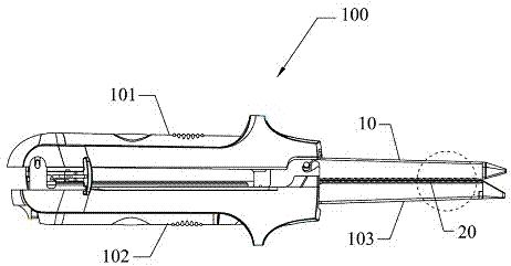
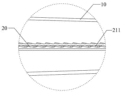
[0023] ginseng Figure 1 to Figure 3 , to introduce a specific embodiment of the linear suturing and cutting device 100 of the present invention. In this embodiment, the linear suturing and cutting device 100 includes upper and lower jaws 101 , 102 that can be closed or opened with each other. It should be noted that the "upper" and "lower" mentioned here do not repr...


PUM


Abstract

The invention discloses a linear suturing and cutting device. The linear suturing and cutting device comprises an upper forceps holder and a lower forceps holder which can be closed and opened mutually. The upper forceps holder comprises a nail anvil, the lower forceps holder comprises a nail cartridge rack, the nail cartridge rack is detachably provided with a nail cartridge, and the inside of the nail cartridge is sequentially provided with a nail cartridge hole which penetrates the surface of the nail cartridge and a nail pushing sheet which is arranged inside the nail cartridge and can slide relative to the nail cartridge hole; the inside of the nail cartridge is also slidingly provided with a trigger sheet, the trigger sheet is provided with a wedge-shaped nail pushing unit which can drive the nail pushing sheet to slide inside the nail cartridge hole, and the nail cartridge hole is inclined to the far end of the nail cartridge. Therefore, when the nail pushing sheet inside the nail cartridge sheet is pushed, the stress direction of the nail pushing sheet is identical to the extension direction of the nail cartridge hole, relatively high friction force between the nail pushing sheet and the inner wall of the nail cartridge hole can be avoided, so that the nail pushing sheet can be pushed more smoothly, and further the surgical difficulty can be reduced.

Description


Claims


Application Information

Patent Timeline
Owner TOUCHSTONE INTERNATIONAL MEDICAL SCIENCE CO LTD
Learn More