Motor assembly for centrifugal fan

A technology for centrifugal fans and motors, which is applied to machines/engines, parts of pumping devices for elastic fluids, pump elements, etc., which can solve the problems of poor hydrodynamic performance of blades, inability to conduct concentrated air flow, and energy consumption of fans. Advanced problems, to achieve the effect of improved fluid mechanics performance, beautiful appearance, and reduced work energy consumption

Active Publication Date: 2014-04-23
浙江盾安轨道交通设备有限公司
View PDF6 Cites 5 Cited by
  • Summary
  • Abstract
  • Description
  • Claims
  • Application Information

AI Technical Summary

Problems solved by technology

The traditional shaft sleeve is provided with an annular mounting plate on the shaft sleeve, and the shaft sleeve and the hub are fastened and installed through a nut assembly. The assembly is more complicated, the overall quality of the fan is heavier, and the energy consumption of the fan is higher.
[0004] The traditional blade and the hub are riveted in parallel, the number of mounting holes on the blade is small, the blade and the hub are prone to loosening, and long-term high-speed rotation may even cause the blade to fall off. At the same time, there is no embossed structure on the traditional blade. The hydrodynamic performance of the blade is poor, and the air volume cannot be effectively concentrated and guided

Method used


Image

  • Motor assembly for centrifugal fan
  • Motor assembly for centrifugal fan
  • Motor assembly for centrifugal fan

Examples


Embodiment Construction

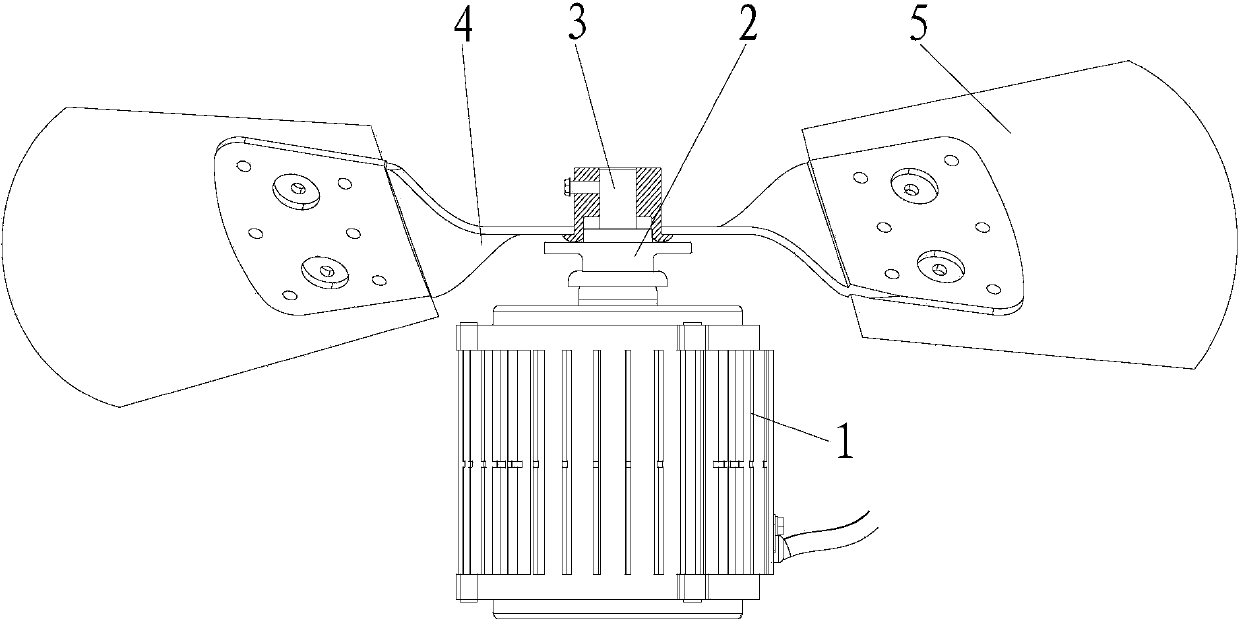
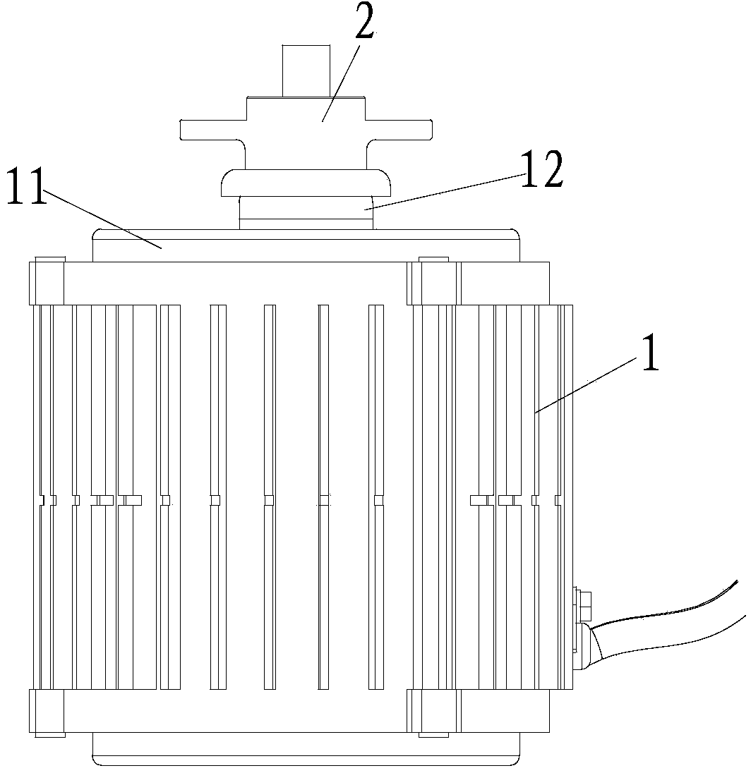
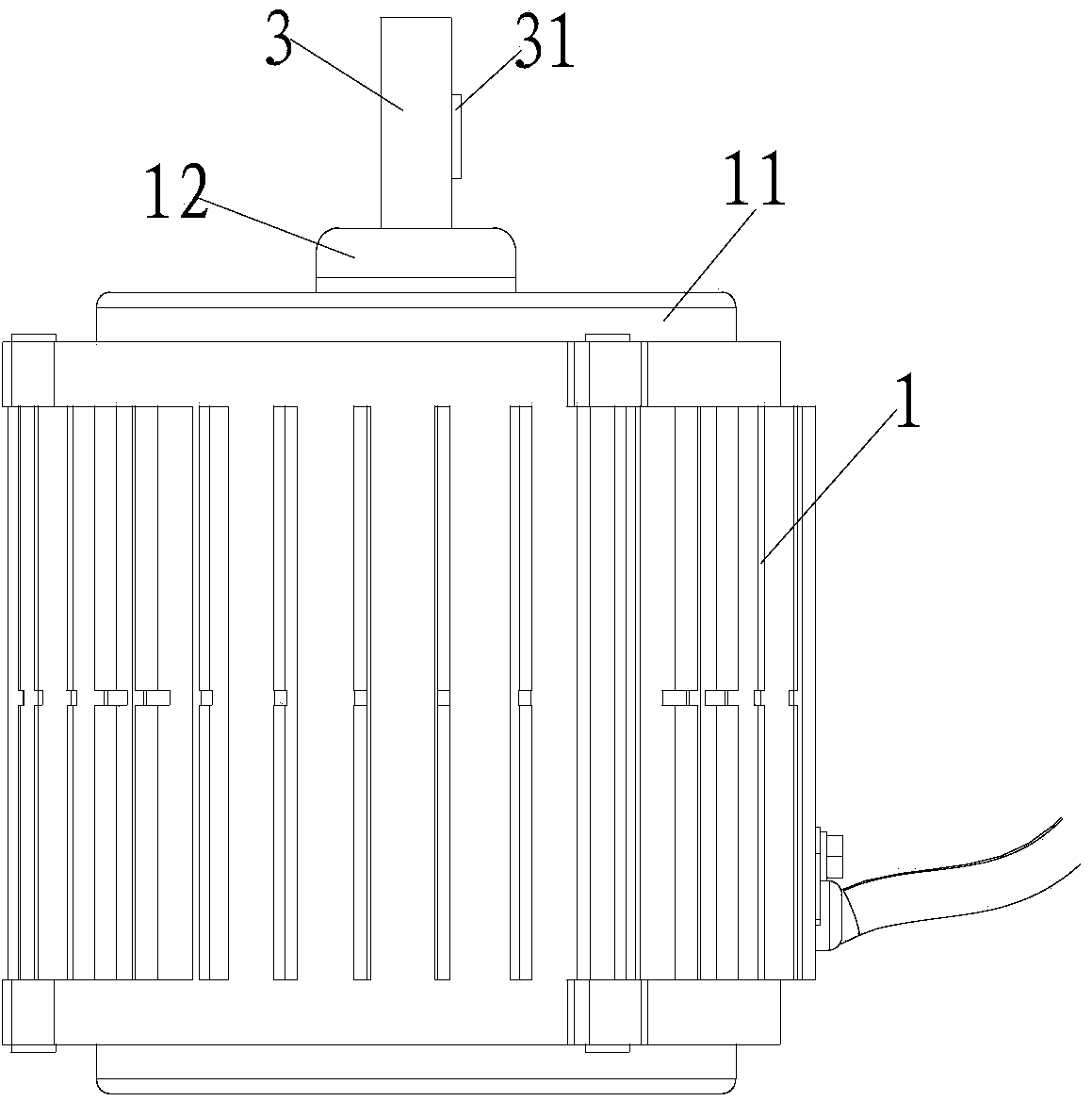
[0026] refer to figure 1 , figure 2 , image 3 , Figure 4 with Figure 5 , a motor assembly for a centrifugal fan in the present invention, comprising a motor 1, a waterproof shaft sleeve 2, a hub assembly 4 and an embossed blade 5, the motor 1 is provided with an end cover 11 and an output shaft 3, and the end cover 11 Cover the front end of the motor 1 through the output shaft 3, the end of the output shaft 3 is provided with a sealing sleeve 12, the waterproof sleeve 2 is installed on the output shaft 3, and the waterproof sleeve 2 includes a mounting sleeve 21 and a waterproof disk 22 , the waterproof disk 22 is covered on the sealing sleeve 12, the hub assembly 4 is installed on the waterproof sleeve 2, the hub assembly 4 includes a hub 41 and a riveted sleeve 42, and the hub 41 is provided with several installation plate 411, the embossing blade 5 is installed on the mounting plate 411, the output shaft 3 is provided with a block-shaped protrusion structure 31, the...


PUM


Abstract

The invention discloses a motor assembly for a centrifugal fan. The motor assembly comprises a motor, a waterproof shaft sleeve, a hub assembly and stamped blades, wherein an end cover and an output shaft are arranged on the motor, the end cover penetrates through the output shaft and covers the front end of the motor, a sealing sleeve is arranged at the tail end of the output shaft, the waterproof shaft sleeve is installed on the output shaft and comprises an installing shaft sleeve and a waterproof disc, the waterproof disc covers the sealing sleeve, the hub assembly is installed on the waterproof shaft sleeve and comprises a hub and a riveting shaft sleeve, a plurality of installing plates are arranged on the hub, and the stamped blades are installed on the installing plates. According to the motor assembly, water and dust can be prevented from entering the motor, the assembly structure is simple and firm, the overall mass of the fan is reduced, working energy consumption is lowered, the blades and the hub can be firmly installed, looseness can be prevented from occurring between the blades and the hub, the fluid mechanics performance of the blades is improved through stamping structures on the blades, and air can be effectively guided in a centralized mode.

Description

【Technical field】 [0001] The invention relates to the technical field of parts and components for a centrifugal fan, in particular to the technical field of a motor assembly for a centrifugal fan. 【Background technique】 [0002] There are two types of fans, axial flow and radial flow, which are divided according to the flow direction of the air when the fan is working. The fan uses the motor to drive the rotation of the blades to transport the hot air out of the equipment. Since the hot air is prone to condensation after cooling, water mist is prone to appear at the motor connection. The traditional motor shaft sleeve only serves as a connection, without waterproof and waterproof. Dust function, water and dust are easy to enter the motor, which may rust the output shaft of the motor, or cause a short circuit of the motor and fail to work normally. [0003] The fan connects the shaft and the fan hub through the shaft sleeve, so as to drive the rotation of the blades and tran...

Claims


Application Information

Patent Timeline
Patent Type & Authority Applications(China)
IPC IPC(8): F04D25/08F04D29/10F04D29/053F04D29/28F04D29/30
Inventor 寿国理
Owner 浙江盾安轨道交通设备有限公司
Why Eureka
Try Eureka