Plastic cap holding linkage clamping rotary capping machine

A technology for plastic caps and capping machines, which is applied in the field of plastic cap clamping and clamping capping machines, which can solve the problems of affecting the service life of the clamping mechanism, wear and tear of the clamping mechanism, and high production costs, and achieve simple structure and extended use. The effect of long life and convenient processing

Inactive Publication Date: 2014-04-23
中粮包装(广州)塑胶有限公司
View PDF5 Cites 9 Cited by
  • Summary
  • Abstract
  • Description
  • Claims
  • Application Information

AI Technical Summary

Problems solved by technology

[0002] In the production process of plastic caps, it is necessary to assemble the plastic outer cap and the inner plug. In the existing plastic cap clamping linkage clamping capping machine, the clamping mechanism and the rotating mechanism generally rotate synchronously, which will cause the clamping mechanism to accelerate. wear, which affects the service life of the clamping mechanism
The existing capping machine has complex structure, inconvenient installation and relatively high production cost

Method used


Image

  • Plastic cap holding linkage clamping rotary capping machine
  • Plastic cap holding linkage clamping rotary capping machine
  • Plastic cap holding linkage clamping rotary capping machine

Examples


Embodiment Construction

[0024] The present invention will be further described below in conjunction with the description of the drawings and specific implementations:

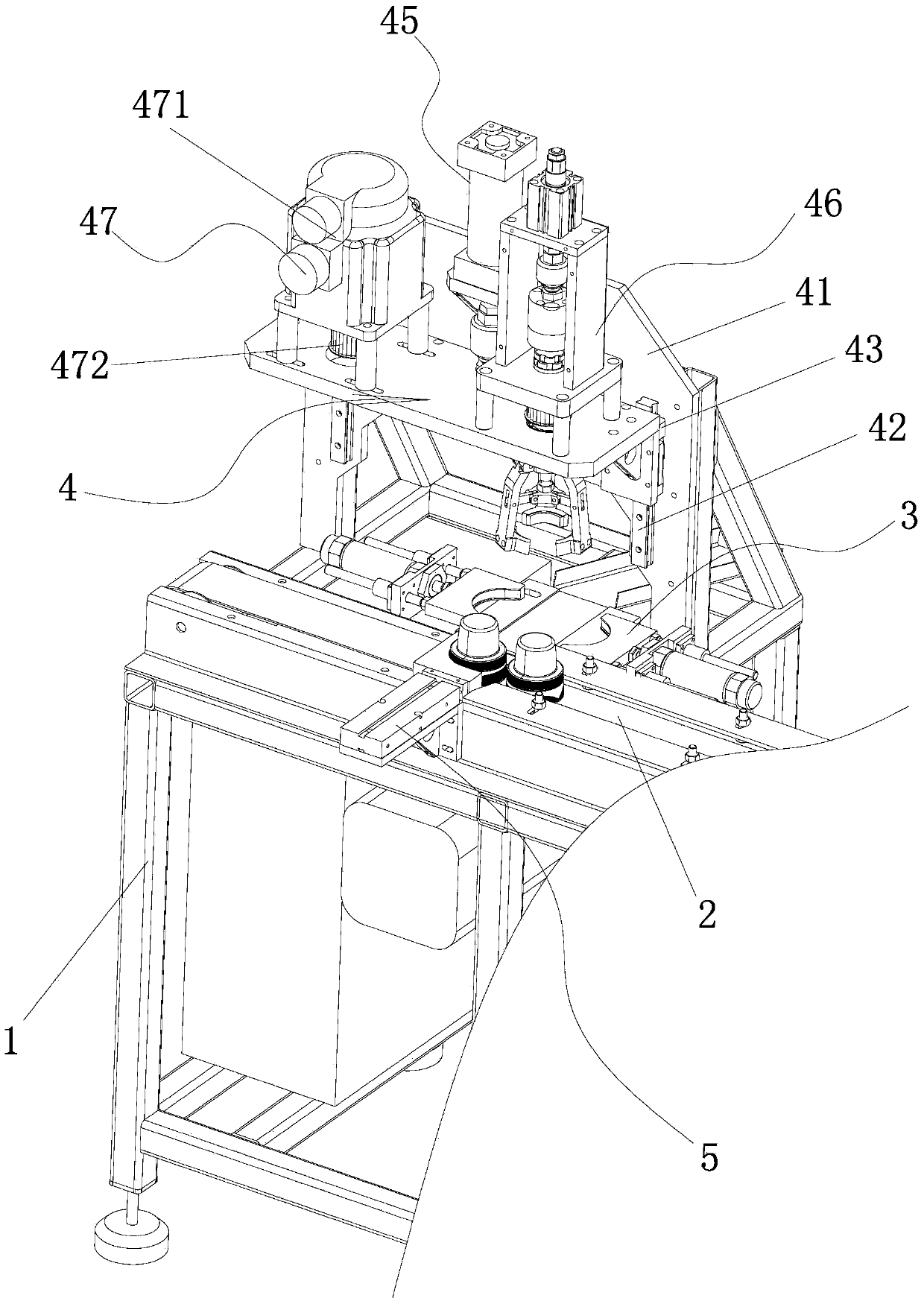
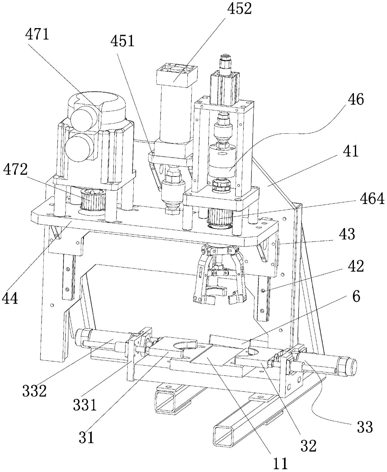
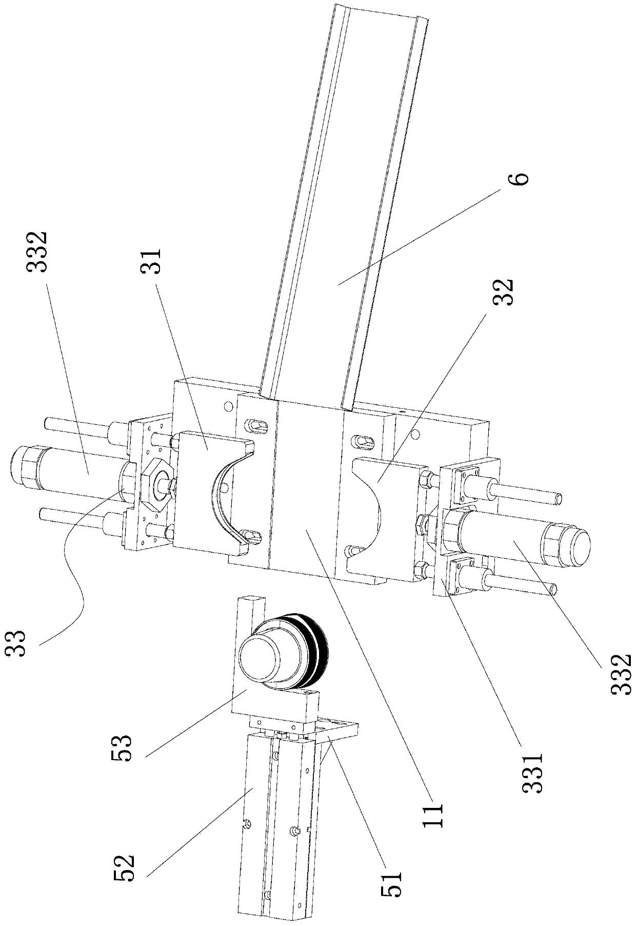
[0025] Such as Figure 1 to 5 The plastic cover clamping linkage clamping capping machine shown includes a machine base 1, a conveyor belt 2 is provided on the base 1, and a machine base 1 on one side of the conveyor belt 2 is provided with a clamping and fixing device. The clamping mechanism 3 of the lower cover is provided on the base 1 on the other side of the conveyor belt 2 with a pushing mechanism 5 that can send the plastic cover on the transmission belt 2 into the clamping mechanism 3, and the clamping mechanism 3 The base 1 on one side is provided with a plastic cover clamping linkage clamping and screwing device 4 capable of clamping the upper cover and screwing the upper cover to the lower cover.

[0026] Such as figure 1 with 2 As shown, the plastic cover clamping linkage clamping and screwing device 4 in the present invention...


PUM


Abstract

The invention discloses a plastic cap holding linkage clamping rotary capping machine. The plastic cap holding linkage clamping rotary capping machine comprises a machine base, wherein the machine base is provided with a conveyor belt, and the plastic cap holding linkage clamping rotary capping machine is characterized in that a holding mechanism which can hold and fix lower caps is arranged on the machine base on one side of the conveyor belt, a material pushing mechanism which can send plastic caps on the conveyor belt into the holding mechanism is arranged on the machine base on the other side of the conveyor belt, and the plastic cap holding linkage clamping rotary capping machine which can hold upper caps and screw the upper caps on the lower caps is arranged on the machine base on one side of the holding mechanism. The invention aims at overcoming the shortcomings of the prior art and providing the plastic cap holding linkage clamping rotary capping machine with the advantages of simple structure, long service life and low production cost.

Description

Technical field [0001] The invention relates to a plastic cover clamping linkage clamping and screwing machine. Background technique [0002] In the production process of plastic caps, it is necessary to assemble the plastic outer cap and the inner plug. The clamping mechanism and the rotating mechanism in the existing plastic cap clamping linkage clamping capping machine generally rotate synchronously, which will cause the clamping mechanism to accelerate Abrasion affects the service life of the clamping mechanism. The existing capping machine has complex structure, inconvenient installation, and relatively high production cost. [0003] Therefore, the existing plastic cover clamping linkage clamping and screwing machine needs to be further improved. Summary of the invention [0004] The purpose of the present invention is to overcome the deficiencies in the prior art and provide a plastic cover clamping linkage clamping and screwing machine with simple structure, long service li...

Claims


Application Information

Patent Timeline
IPC IPC(8): B29C65/56B29C65/78
Inventor 杨光强吴武杰
Owner 中粮包装(广州)塑胶有限公司
Why Eureka
Try Eureka